This USB Powered Audio Power Amplifier Circuit Diagram of multimedia speakers for PCs has single-chip-based design low-voltage power supply compatibility with USB power easy heat-sinking low cost high flexibility and wide temperature tolerance. Impedance speaker is 32 Ohm with Frequency 20 Hz -20 kHz.

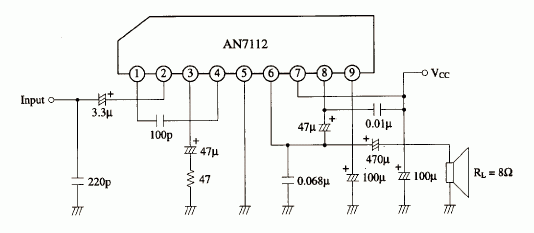
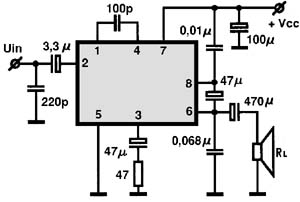
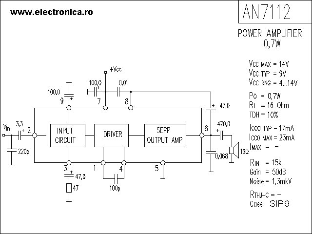
An7112 Power Audio Amplifier Schematic
In this circuit one ic 4558 and 4 Power transistors are used with some discrete components.

Audio Power Amplifier Circuit Diaggram Using An7112. So the LM-386 IC is the heart of the circuit. That is why in an electronic system a voltage amplifier circuit always precedes a power amplifier circuit as shown in block diagram of amplifier circuit Figure 1. LM-386 is a low power audio power amplifier IC.
Power Amplifier Circuit Diagram is still less by looking at the circuit that was so below the finished circuit has been added with gains using two JRC4558 IC the picture IC where it can be seen below. Using 3 ICs in a bridge model. In the second part of the lab you will construct a microphone circuit using a compact electret condenser microphone cartridge.
Amplifiers Module 4 What youll learn in Module 4. INTRODUCTION An amplifier is an electronic device that increases the power of a signal. This IC has good features like short circuit protection load dump protection reverse polarity protection etc.
Its so low power amplifier. Obviously the emitter current of the first transistor becames the base current for the second transistor. This is a.
In order to get large power at the output it is necessary that the input-signal voltage is large. The schematic for 10 watt amplifier is pretty simple the LF351 amplifies the signal voltage and two Power Transistors provide the necessary power amplification. TDA1553 is a monolithic icThis Audio Amplifier Circuit gives 44w output power.
An audio amplifier is an electrical circuit and that. This is a low voltage Amplifier with output speaker stereo 2 X 038 watt. The power is directly taken from the power supply and provided to the 8 Ohms Loud Speaker via two transistors.
The circuit of this amplifier uses operational amplifier as the building block. And using NFB to control impedance is described in Amplifiers Module 32. The amplifier circuit will be equipped with volume control feature by using a variable resistor at the output.
Section 40 Introduction to Impedance and Bandwidth Control. This Schematic Circuit Audio Amplifier use IC AN7105 minimum voltage 15 volt and maximum voltage 95 volt. The circuit described here is fully in tune with the spirit of.
Multisim software is utilized for the construction of audio power amplifier. The audio amplifier will be a self-contained battery-operated component. Use 20v-to 60v for operating this circuit.
Power amplifier circuit is meant to raise the power level of the input signal. TDA2613 is an integrated Hi-Fi audio amplifier IC from Philips Semiconductors. A 6 watt audio amplifier circuit using TDA2613 is shown here.
Module 43 describes some other amplifier circuits that are commonly used to control the values of input and output impedances in amplifier circuits. Stereo Amplifier Circuit Diagram we are going to design here is basically the combination of two mono audio amplifier. LM386 Audio Amplifier Circuit with PCB It was my first mini audio amplifier.
This is low output power or mini amplifier sound. Maximum output power 05 watt. Impedance Speaker 8 Ohm and frequncy 40 Hz - 18 kHz.
Schematic Circuit use the IC AN7112 with minimum voltage 4 Volt and maximum voltage 14 Volt. It is designed to maximize the magnitude of the power f given input signal. With a pair of these devices you could put together an audio power amplifier that could deliver a healthy 40 W into 8 Ω.
October 27 2018. For circuit buffers drivers and booster use multiple transistors and. In the first part of lab1 you will construct a low-power audio amplifierspeaker driver based on the LM386 IC from National Semiconductor.
Audio Power Amplifier circuit diaggram using AN7112. Sixties-style 40 W Audio Amplifier Schematic Circuit Diagram. High Power Class D Audio Power Amplifier using IR2011S.
At the heart of the circuit is IC TDA2822M. In sound electronics the operational amplifier increases the voltage of the signal but unable to provide the current which is required to drive a load. The IC is switch ON switch OFF click proof short circuit proof thermally protected and is available in 9 pin single in line plastic package.
So if the stereo high power amplifier 2 X 1400W Power Output 2800W. In the early 1960s RCA brought out a transistor that was to become truly legendary. TDA2613 Hi Fi audio amplifier Description.
100 Watt Power Amplifier Circuit using MOSFET. OCL system Class B amplifier Multisim software 1. As Sinusoidal wave change the polarity TIP127 provides the power amplification on positive peak and TIP 122 provides.
This IC is in fact mono-lithic type in 8-lead mini. It is cheap and easy to builds for a beginner. We have so many collections wire wiring diagrams and schematics possibly including what is you need such as a discussion of the High Power Audio Amplifier Schematics.
This circuit is given by Emmanuel. And suitable for 9V battery. Sound amplifier circuit using TIP3055 BD140 BD139 BC546 D1 D2 D3 1N4148 Content Sidebar Schematic Power Amplifier and Layout.
Because its easy to build and this IC always popular. Many people also use it. We have collected these discussions here and presentin g it to you.
750W sound amplifier circuit. IRAUDAMP1 High Power Class D Audio Power Amplifier using IR2011S. 2W2W Stereo using 3 LM386 Here is an LM386 stereo audio amplifier circuit 2 watts.
800w High Power Mosfet Amplifier Schematic Diagram Schematic - High Power Audio Amplifier Schematics. -5V Q17 OP Amps in the modulator Startup circuit -Vcc5V U13 U14 Logic ICs -Vcc12V U11 Gate driver IC Protection circuits. Portable and good audio amplifier is still a major concern to many electronic hobbyists and professional.
Darlington amplifier with voltage divider bias is shown in figure. In this circuit the output of one amplifier is coupled into the input of the next one by directly joining emitter of one transistor to the base of Other. IC AN7112 has similarities with IC KA2212 LA4140 TA7313AP.
Amplifiers are an essential part of discrete electronic devices such as audio amps mono stereo speakers etc. Power amplifier is the part of audio electronics. How to make Audio power Amplifier and Repairing.
Here is a circuit diagram of stereo audio power amplifier using IC TDA1553. People are still searching for good portable and battery-operated stereo amplifier. 3 Simplified Block Diagram of Amplifier.
Recomeneded voltage is 9 Volt. Audio amplifiers are simple electronic circuits that can boost weak ACDC signals to a level of higher amplitude. So in this project we are going to design a simple audio amplifier circuit using a C5200 NPN Power transistor.

An7112 Audio Ic Electronic Circuits Tv Schematics Audio
Audio Power Amplifier Circuit Diaggram Using An7112

An7112 Power Audio Amplifier Schematic

Schematic Power Amplifier With Ic An7112 Diy Circuit