Ripple Voltage C Spec 4. Its dual the principle of capacitor amp-second or charge balance states that the average current that flows through an ideal capacitor must be zero.

220 230v Ac To 12v 5v Dc Regulated Power Dc Converter Bridge Rectifier Power Supply Circuit Power Regulators
Active cell balancing redistributes charge during the charging and discharging cycle unlike passive cell balancing which simply dissipates charge during the charge cycle.
Charge Balance Converter Circuit. There are two different categories of active cell balancing methods. This in turn will result in a different open circuit voltage for cell 3 compared to cells 1 and 2 because the open circuit. Application of the principle of charge balance to the output capacitor C leads to i C D V RDn I V0 7 Solution for I yields I nV DR 8 This is the dc component of the magnetizing current referred to the primary.
Buck-boost converter circuit diagram. The effectiveness of the optimal performance generally requires precise knowledge of the circuit parameters for charge balance. In this buck- boost regulator is used to controls the charging process of battery.
Both active and passive cell balancing are effective ways to improve system health by monitoring and matching the SoC of each cell. There are many more VFO variable frequency oscillator. The idea was requested by Mr.
The charge balancebased sigma-delta SD AD converter is a well-known high-accuracy analog-to-digital converter 1 which is used in measurement circuits of load cells force transducers and pressure sensors widely. Inductor volt-second balance capacitor charge balance and the small ripple approximation Buck converter containing practical low-pass filter Actual output voltage waveform vtV v ripple t Actual output voltage waveform buck converter L CR vt 1 2 i L t v L t i C t V g vt t 0 V Actual waveform vt V v ripple t dc component V. The charging system must incorporate the proper charging.
Ripple Current L Spec 5. Because of the switch the input current can only provide charge to output side when switch is open and the time is 1-dT in one T-period. Active balancing requires a more complex larger footprint solution.
The charge-balanced VFC may be made in asynchronous or synchronous clocked forms. Switch open mode and switch close. The linearity of this converter can be improved by adjusting the variable resistor connected to the op-Amp 23.
Peak Switch Currents and Blocking Voltages Worst Case Transistor Specs B. In a dcdc converter circuit the system actually works in two modes. Practical Issues for L and C Components 1.
The battery balance circuit detects the premature battery charge in order to prevent this situation and usually uses resistance as the load. Active balancing attempts to redistribute energy from cells at full charge to those with a lower state of charge. Due to more and more high-accuracy requirement for weighing and force measuring there are a number of research works focused on improving the AD converters for higher.
The boost converter however does not involve the tedious method of converting DC to AC then stepping up the voltage and then converting the stepped AC voltage to. A premature failure of the whole battery. The charge-balanced VFC may be made in.
Energy can be bled from a cell at higher SOC by switching a reservoir capacitor in-circuit with the cell then disconnecting the capacitor and reconnecting it to a cell with lower SOC or through a DC-to-DC converter connected across the entire pack. MATLABSimulink model is used to analyze the converter. From a fully charged state the first and second cells chemical state of charge will be Qmax-Q1Qmax 954 but third cell will be 91.
Buck-Boost Converter Design 1. Buck-boost converter circuit when switch S is on Mode-I Also -V C V O 0 Rightarrow V_OV_C Figure 14. DC Operating Point via Charge Balance.
Charge shuttling and energy converters. This is ideal for electric vehicles to prolong its battery cycle life by preventing cell overunder charging. Let the capacitor be totally charged up before switching on the switch S.
ID in steady-state 3. Principles of converter circuit analysis are introduced and are developed for finding the steady state voltages current and efficiency of power converters. It is made out of low-cost jellybean parts under 3 total.
In this case the battery voltage does not exceed the limit value. A basic dcdc converter circuit known as the buck converter is illustrated in Fig. FD steady-state transfer function 2.
Inductor volt-second balance capacitor charge balance and the small ripple approximation 7 Fundamentals of Power Electronics Chapter 2. Buck converter R values Illustrate via examples Fundamentals Of power Electronics Chapter 2. There are two common VFC architectures.
The design does not use any microcontroller or expensivespecialised battery management chip. Principles of steady-state converter analysis Buck converter containing practical low-pass filter Actual output voltage waveform v t V v ri pp le t Actual output voltage waveform buck converter L CRv t 1 2 i L t. Instead of wasting all that energy as heat an active cell balancer efficiently balances cells with tiny converter circuits that pass energy from the highest voltage cells to the lowest voltage cells.
When the switch S is closed as shown in Fig. 13 -V S V L 0 Rightarrow V_SV_LLfracdidt Figure 13. Hence to determine the voltages and currents of dcdc converters.
The circuit boosts the voltage from the supply hence named as boost converter. Charge shuttling is used to actively. Thus active cell balancing increases system run-time and can increase the charging efficiency.
There are two common VFC architectures. Charge balance control is one of the prior choices that enables the converter to operate at its optimal chargedischarge slew rate so as to achieve fast transient response. Principles Of steady-state converter analysis Develop techniques for easily determining output voltage of an arbitrary converter circuit Derive the principles of inductor volt-second balance and capacitor charge amp-second balance.
Promoting cost-effective sustainable transportation. The current-steering multi vibrator VFC and the charge-balance VFC 1. The second law is the charge balance 22 which means the input charge equal to output charge.
A PV system require proper battery charge controller to balance the power flow from PV system to battery and load such that photovoltaic power is utilized effectively. The current-steering multivibrator VFC and the charge-balance VFC Reference 1. Assignments include simulation of a dc-dc converter analysis of an inverting dc-dc converter and modeling and efficiency analysis of an electric vehicle system and of a USB power regulator.
There are many ways to converter a lower DC voltage to a higher one. Voltage-to-Frequency Converter VFC and Frequency Counter Make a Low-Cost Versatile High-Resolution ADC. Cell balancing is a way of compensating for these weaker cells by equalizing the charge on all the cells in the chain thus extending the battery life.
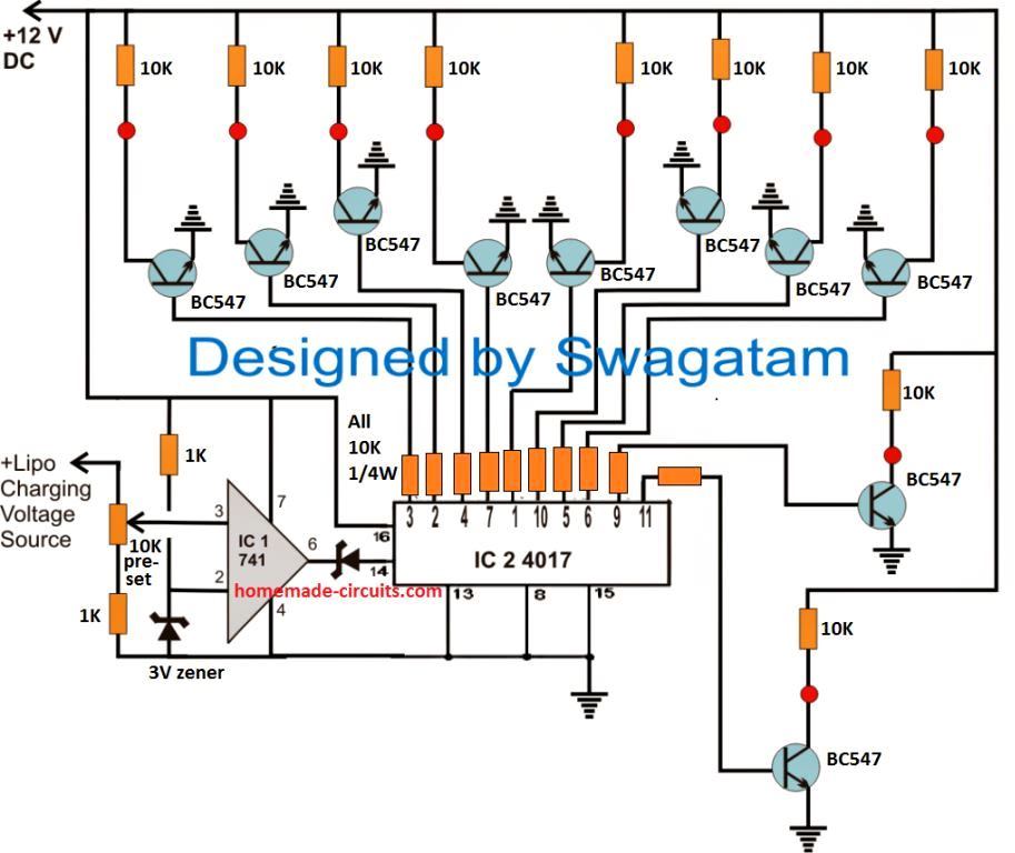
The post discusses a relatively easy lipo battery balance charger circuit which is designed to continuously scan and charge the connected cells of the battery. Emil Jan Thomas Baticulon. So the conversion ratio of the flyback converter is similar to that of the buck-boost converter but contains an added factor of n.
1 1-5 A single-pole double-throw. The life of a rechargeable battery can be extended through the use of an intelligent charging system. So we can say cell 3 is imbalanced by 44.

Dfferential Temperature Relay Switch Circuit Electronics Circuit Electronic Schematics Diode
Lipo Battery Balance Charger For Charging Of Series Connected Lipo Cells Homemade Circuit Projects

4s 40a Li Ion Lithium Battery 18650 Charger Pcb Bms Protection Board With Balance For Drill Motor 14 8v 16 8v Lipo Cell Module Sweet Cargador Taladro Motores

3d Stereo Sound Circuit Split Stereo Signal Balance Indicator Circuit Electronics Projects Audio Amplifier