The modulation is a process of varying the parameter of a carrier signal in accordance with the instantaneous value of the message. With circuit diagram and Arduino source code.
555 Dc Motor Speed Control Motor Speed Circuit Diagram Electronic Circuit Projects
The advantage of this circuit is it can be used to drive stepper motors having 2-10 steps.

Driver Speed Control Circuit. The IC then increases the motor voltage so that the original speed is recovered. It senses the increase in the motor-current when the rotation of the motor slows down due to a load. These are frequently used on radio-controlled models which are electrically powered with the change most frequently used for brushless motors providing an electronically produced 3-phase electric power low voltage source of energy for.
Miniature electronic speed controls are used in electrically powered radio controlled models. The setting of P1 determines the phase of the trigger pulse that fires the triac. DC FAN Speed Regulator Circuit DC FAN Motor Speed Controller Regulator Circuit Works ON Principle of Pulse Width Modulation PWM technique By Using This Technique Controlling Of DC Motor Speed is very Smoothly And Noise Free.
It can be seen from the circuit diagram shown in figa that at the instant of turning on of the SCR gate current flows through R L and diode. Arduino DC motor speed and direction control with L293D motor driver. In addition to controlling the motors speed its direction of rotation can be also changed using this circuit.
Before going any further lets discuss more about the basics of. Transistor or Mosfet as external circuit to drive control the speed and direction of DC motor An external transistor or mosfet is a best choice to drive a 12 volt motor using stm32 microcontroller. This triac-based 220V AC motor speed controller circuit is designed for controlling the speed of small household motors like drill machines.
Many DC motor speed control circuits have been published here but this is the first one using NE555 timer IC. The speed is controlled using a potentiometer connected to pin A0 and the direction of rotation can be changed with a pushbutton connected to pin 8. This voltage control is realized by an inverter in the output part of the control circuit driver.
The circuit incorporates a self-stabilizing technique. The technique of controlling motor speed using PWM signals is very common. These are 12-volt DC variable-speed motor controller circuit using CMOS.
Full-size electric vehicles also have systems to control the speed of their drive motors. DC Motor Speed Control Circuit Diagram Connect 5 volts pin of the Arduino with the 5 volts pin of the L298n motor driver module and one side pin of the 10K ohm potentiometer. Technically stepper motor driver circuit is a Decade Binary Counter circuit.
We can adjust the speed of 12V small motor. An electronic speed control is an electronic circuit that controls and regulates the speed of an electric motor. Pulse Width Modulation PWM technique is used where its signal is generated by PIC 18F4550.
Stepper Motor Driver Circuit. The speed of the motor can be controlled by changing the setting of P1. A PWM circuit based on timer NE555 is the heart of this circuit.
The control circuit connected with the hall sensors are in fact blind and respond entirely to the hall sensor signals in order to produce the required feed backs to the electromagnet coils. Even 6V or 9V Motor this can be used too. It is easy and uses a few components that IC digital and transistor driver as main.
It may also provide reversing of the motor and dynamic braking. For example an electric vehicle DC motor controller for a brushless DC BLDC motor has different design and working principles compared to an industrial DC. The PWM signal will send to the motor driver to vary the voltage supply to the motor in a desired speed.
Control the speed and torque. It is an informative collection of. The specifics of a DC motor controller depend on the motor type brushed brushless stepper and functionality of the device that uses this motor.
By Dilip Raja May 15 2015 21. For those who are not aware PWM or Pulse Width modulation is a modulation technique in where the width of the output pulse varies with with respect to time. 180 degree Phase Control.
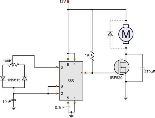
V T V D V G I G R L. Fundamentals of MOSFET and IGBT Gate Driver Circuits LaszloBalogh ABSTRACT The main purpose of this application report is to demonstrate a systematic approach to design high performance gate drive circuits for high speed switching applications. A simple DC motor controller circuit using NE555 is shown here.
19 Amp Motor Driver Circuit For Powerful Robot Projects A motor driver circuit designed specifically for robotic projects using high power collector motors with or without PWM modulation with a BI-Direction Motor Speed Control Circuit LM324 Mosfet IRF9540 IRF540. P1 potentiometer varies the speed of. The term ESC stands for electronic speed control is an electronic circuit used to change the speed of an electric motor its route and also to perform as a dynamic brake.
First circuit is for transmitter and another circuit is for the receiver. Therefore since the rotational speed changes whenever the load torque changes the speed control mechanism will only have to change the input voltage whenever a change in the speed is seen in order to maintain a constant speed on the PR line. The DC Motor driver L293D is used in this project as it.
They use the principle of PWM motor control mode. The base of transistor mosfet is connected to stm32 output pin and motor will be inserted between collector of transistor. Attach the GND pin of the Arduino with the GND pin of the L298n module and another side pin of the 10K potentiometer.
The above fact actually makes the designing of a 3 phase BLDC motor controller pretty easy the simplicity also becomes further aided with the easy availability of the universal 3 phase H bridge driver IC such as the. This motor speed controller uses a single IC LM1014 to control the speed of a DC motor. The circuit shown in figure can trigger the.
This circuit uses similar PWM technique to control motor speed and uses IC 555 to generate PWM signals.
Pin On Circuit

Electrical Page Dc Motor Control Circuit Diagram Circuit Diagram Electronic Circuit Projects Electrical Engineering

12 Volt Dc Motor Speed Controller Motor Speed Circuit Diagram Electronic Circuit Projects

Pin On مدارات الکترونیکی