It translates the sub sonic signals into the audio. It could be used as an earthquake detector.
Sample Circuit To Measure Geophone Output Download Scientific Diagram
I can expand in an answer.
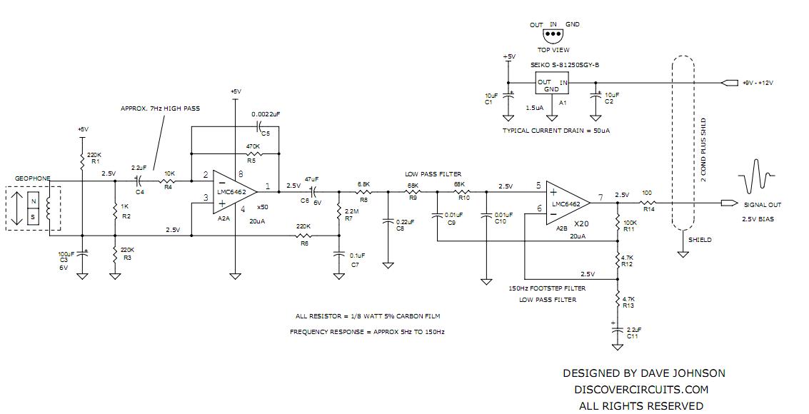
Geophone Detector Circuit. Geophone frequency response is not good for detecting distant earthquakes and are designed to detect vertical motion - also not so good. You will need to adjust the geophone bias resistor value R1 to match the specifications of your model. Click on Drawing Below to.
In seismic exploration based upon field-proven ION Sensor technology. 10 Hz 25 10 Hz 25 Typical spurious Frequency. So much so that I decided to try it for myself.
In the traditional geophone transducer drive circuit and detection circuit are the all components the recorder takes the place of communication circuit and data storage unit. Hobby Circuit designed by. In 2-D and 3-D surveys.
GS-32CT Geophone Specifi cations are subject to change without notice Frequency Response Curves 395 Ω 635 Ω Frequency Natural Frequency Fn. Human Traffic Footstep Detector Preamp - This circuit uses a surplus geophone to detect human footsteps from 100 feet away. Detector for Human Footsteps - This circuit uses a surplus geophone to detect human footsteps from 100 feet away.
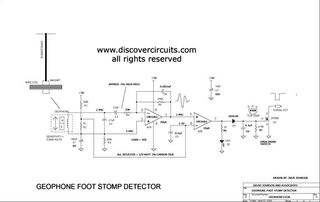
A home made geophone is made from a strong magnet a coil of wire and a rubber band. GS-14 Geophone PRODUCT DETAILS. It works by generating a wave from the surface and measuring the reflections bouncing back from the layers below use.
The GS-14 has been used as a reliable component in sonobuoys smart fuses and intrusion-detection systems. If it was an AD 524 I remember at the time they were. If you are going to pound on the ground with a sledge hammer or shotgun slugs and get echos from rock layers OK.
Geophone is Improved by using Capacitive Detection Circuitry Noise does not Limit Capacitive Geophone at Low Frequency Limits on Resolution of a Capacitive Geophone are Better than the Resolution of a Guralp CMG-40T Broadband. I have always been fascinated with how seismic detection can see what is under the ground. Last time used fed into a comparator 234 Calrad 1 W 8Ω with 3 coins but that only gives presence of impulse- not amplitude.
Might feed it. We depend on sturdy technical force and continually create sophisticated technologies to meet the demand of Geophone Sensor Circuit. The function of level detector 10 is to remove the low level noise from the signal by providing a threshold and to provide at its output 25 a series of square wave pulses.
The circuit uses the OPA376 in a standard non-inverting AC amplification circuit commonly employed for microphones geophones and other small signal AC sensors. So Profi Tools supply you best benefit of money and were ready to create with each other with Geophone Sensor Circuit Geophone Instrument 3 Component Geophone Cableless Seismic We welcome customers business associations and friends from all parts of the world to contact us and seek cooperation for mutual benefits. February 10 2017 In.
It was designed for monitoring the MexicoUSA border. Force-balance seismometers mounted radially from the center of the load plate measure the deformation of the pavement in response to the load. Geophone included transducer drive circuit detection circuit communication circuit and data storage unit.
Moving-coil velocity detector Circuit simulation. There are 4 separate inputs and each of these can have a number of sensors. The circuit is sensitive enough to detect the vibrations of a nearby foot stomp.
250 Hz 250 Hz Resistance Distortion Harmonic Distortion with coil to case velocity of 07 insec 18 cmsec p-p 12 Hz. Its 10mv sensitivity can detect light flashes from a range of over 100 feet. Low distortion combined with excellent specifications provide high-fidelity data.
Self-test Circuit Design of the Geophone As a sensor converting the seismic signal to electrical signal the detector is a key component of the digital geophone. Geophone Detector Circuit using LMC6462. Geophone Detector Circuit using LMC6462.
The GS-14 is a miniature self-generating velocity detector designed for vibration monitoring in rugged environments. Output around 2-5 mV. A gain of 20 db is normally adequate to amplify a typical geophone output to a level which can be detected by level detector or comparator circuit U2.
You can tell which of the 4 circuits is active thereby you know where there is action. Detector for Human Footsteps - This circuit uses a surplus geophone to detect human footsteps from 100 feet away. Home Made Geophone Detects Foot Stomp.
Some typical offsets are 0 200 300 450 600 900 1200 and 1500 mm. Typical Circuit 100x Ampifier 10-7 10-6. Using Geophone Sensors to detect seismic events.
This preamp part of the system draws about 50 micro amps from a 12 volt supply. The PSR-1A is a Vietnam era seismic sensor designed to detect ground vibrations. I made up several circuits using accelerometers like those I posted and used a single AD524 programmable gain op-amp.
This preamp part of the system draws about 50 micro amps from a 12 volt supply. The extended bandwidth allows the full potential of 2-ms24-bit recording systems to be realized. Its performance is related to the function of the whole system so it is necessary to check the geophone first before the seismic data acquisition.
The coil makes the circuit immune to normal room lights. Detectors earthquake detector Geophone Detector Circuit LMC6462 geophone sensor Geophones Electronic Circuits Seismic Monitors Sensors. The SM-24 geophone element is designed to offer the highest performance.
For natural seismic activity you will need gain of a million or so. It was designed for monitoring the MexicoUSA border. It uses wires between the geophones and the box.
For a 20 db amplification U2 may be adjusted so that U2 provides a positive output voltage of 5 volts when the input is negative and exceeds 25 volts. You can make a cheap geophone by gluing a few penneys to the voice coll of a small speaker pref. Hobby Circuit designed by Dave Johnson PE-February 15 2002.
It withstands extreme shock with no change in performance characteristics. Tutorial of how to make a simple geophone for Ghost Hunting You will require 5 parts1 9v project Box enclose2 2oz lead fishing weight3 Piezo - suggest get. It was designed for monitoring the MexicoUSA border.
Geophone is a kind of typical seismic sensors after years of development the structure and technology has been quite mature but in recent years with the development of measuring needs for micro-seismic events the traditional geophone appeared insufficient this article through. The signal from a seismic sensor such as a geophone not shown is amplified and applied to the input at terminal 11 of level detector 10. The deflections measured at.
Published 21022011 Filed in Audio Video. A high z something like audio 34 from BGMicro best bet is the seismometer.

Working Principle Of A Geophone Download Scientific Diagram
Geophone Footstep Detector Preamp Amplifier Circuit Circuit Diagram Seekic Com
Home Made Geophone Detects Foot Stomp Measuring And Test Circuit Circuit Diagram Seekic Com
Geophone Detector Circuit
