Overvoltage protection is a characteristic of a power supply system which somehow deals with the voltage across the load side when the input voltage exceeds the pre-set value. In normal use the 12V supply goes to the output via the reverse protection diode and fuse.

Pin On Electronics
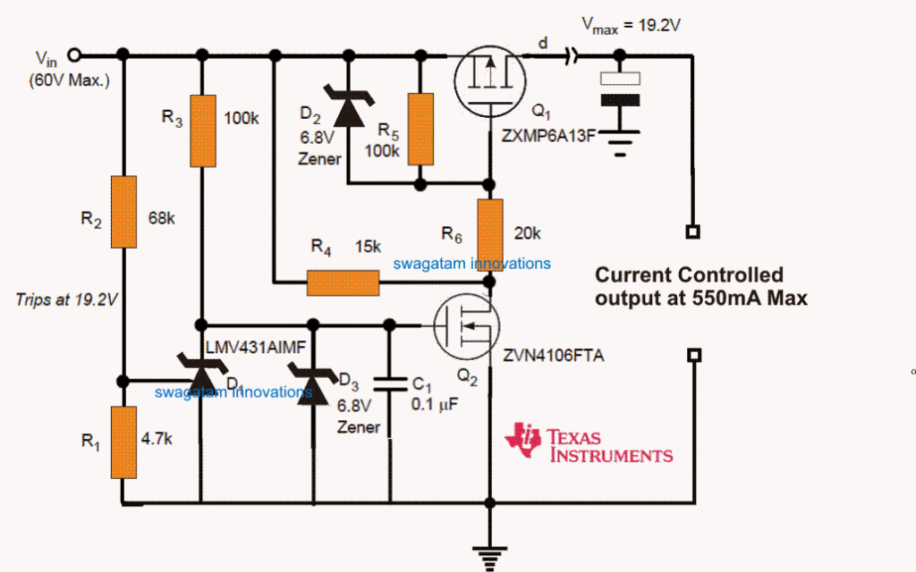
This circuit provides low voltage and high voltage tripping mechanism to protect the load from damage.
Overload Indicator And Overvoltage Protection Schematic. Overload protection circuit for regulator IC. Refer to the schematic shown below and have look at some of the panorama of the project explained below. And for the higher voltage one the Circuit will be fully damaged.
Overvoltage-lockout OVLO thresholds are set using external resistors R1 and R7. 2 4 Design Considerations for V in and R in. The magnetic element provides protection against overcurrent and thermal element protects the circuit from overload where it operate on inverse time curve ie.
Simulate this circuit Schematic. General applications of these systems are used in agriculture motors water pumps and etc. The Thyristor or SCR Silicon Controlled Rectifier can be used to provide overvoltage protection in a power supply circuit.
A much simplified schematic of the input of the. This is an overload protection circuit for voltage regulator IC. The output voltage can be controlled by the touch switch.
In this article we will discuss the different control structures like timers and comparators of the under voltage and over voltage protection. Overvoltage and Under Voltage Protection Block Diagram Circuit Operation As shown in the above block diagram the mains AC power supplies the power to the whole circuit and for operating loads by using relays and also for tripping the load lamps in the presence of the input voltage which falls above or below a set value. The LED is the working indicator of the stabilized power supply and the resistance R1 is the.
So thats why I decided to make another Tutorial which can provide perfect protection against the Overvoltages. Adjustable undervoltage protection range is between 45V and 24V. Slow blow fuses and overload relays are used against overload protection whereas thermal magnetic circuit breaker are used for both overcurrent and overload protection.
In some situations where the input voltage is higher than expected we always use an overvoltage protection or crowbar protection. Overloading a voltage stabilizer might also. These LED lights can we indicated that the required voltage on the electronic components is quite high.
Because if the DC current flowing to the speakers must be disconnected as soon as possible. Why we need a Short Circuit Protection. The Importance of an Overload Protection Circuit.
A crowbar circuit shown in Figure 1 can protect your device from overvoltage. So this Voltage sensor has no protection against the overvoltage and can easily damage the Arduino Input Pins. Often We use a 7812 regulator 12V power supply.
For output currents ranging from 25 Amperes to 10 Amperes. When the voltage is less than the preset level the base terminal of the Q2 is high and as it is a PNP transistor it turns OFFAnd when Q2 is in off condition the base terminal of Q1 will be LOW and it allows the current to flow through it. The Under Voltage and the overvoltage protection circuit is a circuit which protects you from The higher Voltages and the Lower Voltages Conditions.
This design provides a low-cost underovervoltage protection since this is just comprised of few components. Voltage fluctuations in the electric power supply have a very poor effect on connected load. By detecting the high voltage the circuit can fire the thyristor to place a short circuit or crowbar across the voltage rail to ensure it does not rise to high in voltage.
Working of Overvoltage Protection Circuit. It will be too hot and may damage. Using the TL431 for Undervoltage and Overvoltage Detection Figure 6.
While working with high power amplifier designs two things become crucial the protection of the amplifier and the protection of the speakers from an accidental over current influx. The Zener is chosen to be slightly higher. This is because of the High Potential.
This circuit is also equipped with over-current protection where there are LED indicators that work when the power supply has a high current surge then the led will light up. Current limiting arrangement regulates the output voltage of the LM317 to limit the current flow above a fixed value. Loudspeaker Protection Circuit is really simple.
The following article explains 2 simple amplifier short circuit or overload protection circuits for safeguarding amplifiers from burning. Adjustable overvoltage protection range is between 6V and 36V. Here it comes the circuit.
Overvoltage Crowbar Sensing Circuit This overvoltage protection circuit OVP protects sensitive electronic circuitry from overvoltage transients or regulator failures when used in conjunction with an external crowbar SCR. D2 Q2 D1 Q1 R S 400Ω R G R LIMIT R LIMIT- S 400Ω 2 3 AD620 8 1 V IN I IN. Loudspeaker Protection Circuit is really simple but the function Loudspeaker Protection Circuit is very important because the Loudspeaker Protection will provide protection to Loudspeaker and other component.
A particular stabilizer unit may be rated for handling a maximum specified limit of power beyond which its effects may start diluting or might become inefficient. Comparator With Adjustable Threshold And Near Rail To Rail Output Rsup must be chosen to minimize IKA into the device to have a correct Vka value. The LM317 has a maximum operating current of 15 Amperes with an internal current limiting and thermal overload protection.
This can be used to protect loads like motors. These fluctuations of over voltage and under voltage protection system are produced by many reasons which are like voltage surges limiting overload and etc. The OVP device can be understood as a firewall between the application and the external world represented by the power supply AC adapter USB etc allowing.
For the Lower Voltage You can see some flickers in the Lights. The tripping time becomes less when current increases. The adjustable DC-regulated power supply has complete protection functions.
And Transil to break the circuit in case of extreme overload. When the input voltage reaches 15V the Zener conducts setting up a voltage across R2. If its load is a short-circuited or use too much current.
But the circuit is already designed with an additional overcurrent protection. Other Tools and Components. My point is that the diode should have an activation voltage bigger than 12V we can say 13V for safety reasons and since the power supply itself has overcurrent protection it will automatically shut down once the diode is ON.
AD620 in-amp is shown in Figure 1 showing the input differential transistors and their associated protection parts. Some in-amps have built-in overload protection circuits in the form of series resistors. The device senses the overvoltage condition and quickly crowbars or.
Other modern and safe devices are integrated circuits known as Overvoltage Protection OVP devices. The overvoltage and overcurrent points can be continuously set and can be previewed. In this case 15V.
Rsup is limited by IKA as shown in Equation 2 where IKA must be larger than IKAmin.
Overload Indicator And Overvoltage Protection Schematic


Simple 220v Over And Under Voltage Protection Circuit
Over Voltage Protection For Automotive Load Dump Homemade Circuit Projects

Features Multiple Protection Features With Built In Overload Short Circuit Thermal Over Charge And Over Voltage P Surge Protection Surge Protector Sockets