100W MOSFET Power Amplifier Circuit Diagram. This is a 5 watts Audio Booster circuit using 4 transistor.

My Circuit
Lets look at this circuit.

25w Audio Amplifier Circuit Using Tda2613. The boosted signal is then goes to the next stage Power amp and Protection circuit. Power Amplifier Circuit 25 Watts. Up to 30W output power into 8 ohms.
The only change I made was a suggestion elsewhere to bump the capacitor from Pin 3 of the lm386 to the ground to a 50uF capacitor to help reduce more hum on the output. Which can increase the power for a speaker by about 4 to 6 watts. 6 Watt Hi-Fi Audio Amplifier Circuit.
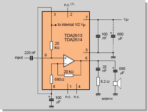
Its amplifiers circuits are designed to working with a minimum of external parts. The 6 watt audio amplifier circuit using TDA2613 are shown here. Admin May 23 2018 May 23 2018 3.
6 watt Hi Fi audio amplifier using TDA2613. It is cheap and easy to builds for a beginner. Preamp circuit was built around op-amp to boost the input signal.
Many people also use it. The IC is switch ON switch OFF click proof short circuit proof thermally protected and is available in 9 pin single in line plastic package. A 6 watt audio amplifier circuit using TDA2613 is shown here.
From 4 transistor amplifier above. A 6W audio amplifier circuit using TDA2613 is shown here. TDA2613 is an integrated Hi-Fi audio amplifier IC from Philips Semiconductors Read More.
The IC is switch ON switch OFF click proof short circuit proof thermally protected and is available in 9 pin single in line plastic package. Using the PCB provided here it will take no more than 10 minutes to build this circuit. We should have made up an appropriate cable as the lack of shielding on the input was very audible indeed.
5 watts 4 transistors Booster Circuit. TDA2613 is an integrated Hi-Fi audio amplifier IC from Philips Semiconductors. The circuit operates from a single 24V power supply as indicated in TDA2613s datasheet.
A 6 watt audio amplifier circuit using TDA2613 is shown here. The 6 watt audio amplifier circuit using TDA2613 are shown here. A 6 watt audio amplifier circuit using TDA2613 is shown here.
TDA2613 Hi Fi audio amplifier Description. TDA2613 is a Hi-Fi integrated audio amplifier IC from Philips Semiconductors. Im using your.
Open loop gain typically 90dB. TDA2613 is a Hi-Fi integrated audio amplifier IC from Philips Semiconductors. TDA2613 is an inte.
The IC is ON OFF button click proof short circuit thermal protection and are available only in the 9-pin plastic package inline. Description A 6-watts audio amplifier circuit using TDA2613 is shown here. Typical THD of 0015 1kHz 20W output.
A 6 watt audio amplifier circuit using TDA2613 is shown here. 2W2W Stereo using 3 LM386 Here is an LM386 stereo audio amplifier circuit 2 watts. TDA2613 is an integrated Hi-Fi audio amplifierIC from Philips Semiconductors.
TDA2613 is a classic integrated Hi-Fi audio amplifier from Philips. TDA2613 is an integrated Hi-Fi audio amplifier IC from Philips Semiconductors. A 6 watt audio amplifier circuit using TDA2613 is shown here.
Because its easy to build and this IC always popular. In this tutorial we will build a 25W Amplifier using TDA2040. Screened cable solved the issue.
TDA2613 is an integrated Hi-Fi audio amplifier IC from Philips Semiconductors. TDA2613 Hi Fi audio amplifier Description. 70mA quiescent current typical Download 25W Hi-Fi Audio Amplifier based LM1875 circuit kit manual.
It is nothing but a non inverting amp with a closed loop gain of about 20. The IC is ON OFF button click proof short circuit thermal protection and are available only in the 9-pin plastic package inline. The LM1875 is a wide power amplifier with very low distortion and high-quality efficiency for audio applications.
LM386 Audio Amplifier Circuit with PCB It was my first mini audio amplifier. The sound is definitely louder. TDA2613 Hi Fi audio amplifier Description.
Using 3 ICs in a bridge model. A GREAT SOUNDING LM386 AUDIO AMPLIFIER circuit. TDA2009 IC is a hi-fi Class AB stereo amplifier in a multi watt package.
TDA2613 Hi Fi audio amplifier Description. SN ratio in excess of 100dB. Now we were able to test the circuit with both MP3 audio and tones from an Arduino.
In the given 6 Watt Hi-Fi Audio Amplifier Circuit TDA2613 is wired to operate from a single supplyCapacitor C4 is the input DC decoupler while capacitors C5 C6 are power supply filters. It is designed to maximize the magnitude of the power f given input signal. In sound electronics the operational amplifier increases the voltage of the signal but unable to provide the current which is required to drive a load.
Input audio is fed to. TDA2613 is an integrated Hi-Fi audio amplifier IC from Philips Semiconductors. TDA2613 Hi Fi audio amplifier.
Here is the diagram of a 25 Watt power amplifier circuit made of TDA2009 IC. 94dB supply rejection ratio. It is actually a dual audio power amplifier that is designed specifically for very good quality stereo applications.
We change some devices and increase the supply voltage level. POWER AMP AND PROTECTION CIRCUIT. TDA2613 Hi Fi audio amplifier schematic circuit diagram.
I am doing so. And suitable for 9V battery. It gives power is 20 watts into a 4 ohms or 8 ohms load on 25V power supplies.
Power amplifier is the part of audio electronics. 25W Audio Power Amplifier. A 6 watt audio amplifier circuit using TDA2613 is shown here.
TDA2613 is an integrated Hi-Fi audio amplifier IC from Philips Semiconductor. Audio power amplifier design. A 6 watt audio amplifier circuit using TDA2613 is shown here.
Variable resistor R3 is used adjust the gain of this preamp circuit. Using a phone as an audio source this was connected to the amplifiers input. 6 Watt Hi-Fi Audio Amplifier Circuit using TDA2613 IC 6 Watt Hi-Fi Audio Amplifier Circuit using TDA2613 IC.
25w Audio Amplifier Circuit Using Tda2613


6 Watts Audio Amplifier Circuit With Tda2613 Hi Fi Electronics Area Audio Amplifier Amplifier Hifi
Tda Series Audio Amplifier Book Electronics Projects Circuits

Pin On Amplificador De Audio