Audio amplifier Week 2. Circuit diagram of the LM386 based audio amplifier is shown in the circuit.
Audio Amplifier Circuit Using Stk0060

You can run with.

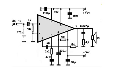
Audio Amplifier Circuit Stk060. The simple Audio Amplifier circuit appears in the above schematic. Furthermore there is a huge range of semiconductors capacitors resistors and ICs in stock. Electronics Projects Sanyo STK Amplifier Schematics audio amplifier circuits ic amplifier Date 20190803.
The maximum signal input before output-peak clipping at 1 MΩ load is 06 V rms for 3 V rms output. The LM386 is a type of operational amplifier Op-Amp. 2W2W Stereo using 3 LM386 Here is an LM386 stereo audio amplifier circuit.
Audio Schematics Service Manuals. Control PIN 5 is the purpose of 23Vcc inside the 555 timer IC so we can change this 23Vcc voltage through this PIN. 2N3055 MJ2955 Schema and Layout for PA.
Schematic Diagram Of The Conventional Darlington Pair Amplifier Scientific. 260 Watts audio amplifier This. Tube Audio Amplifier Circuit.
Circuit Diagram Circuit Operation. In an amplifier circuit the LM386 takes an audio input signal and increases its potential. This article enforces circuit datasheet pinout equivalent and other details about the TEA2025 audio amplifier.
Emitter Follower Darlington Amplifier. The transistors are connected based on the necessity. For increasing gain you may cascade the stages.
Electronic Stereo Volume Control M62429 TK. The circuit works in the basic concept of Transistors. Bootstrap AUDIO circuit using transistor.
5 Channel Portable Audio Mixer. Each circuit below is presented as a definition-by-example and includes step-by-step instructions with formulas enabling you to adapt the circuit to meet your design goals. Bootstrap AUDIO circuit using transistor.
STMICROELECTRONICS TEA2025BAudio Power Amplifier AB 2 Channel 47 W 3V to 12V DIP 16 Pins. 2N3055 MJ2955 Schema and Layout for PA. 3 way active crossover 4 Way Crossover Schema.
DIY and Hi-Fi Audio Schematics. Microphone circuit The audio amplifier project is more difficult and time-consuming than the microphone pre-amp so part of week 2 may be used to finish the audio amp. Which is a 4-transistors complementary push-pull amplifier that shows the basics of audio amplifier design.
Sanyo production STK series power amplifiers integrated belonging to the original circuit diagrams diagram of the manufacturer SANYO is the problem will not be a market original NGO integrated hard to find even copy the original. This gives us a 250 mW amplifier. Soldering and hardwiring can and should be done outside lab.
Four electrolytic capacitors are used in this circuit. Operating voltage from 20v dc 12v dc 10v. Audio Amplifier Circuit.
TEA2025 is a stereo audio amplifier. 190w Rms Darlington Car Amplifier Tip142 Tip147 Sg3525 Converter Electronics Projects Circuits. The circuit of the audio amplifier consists of a transistor a device to apply the input signals and a speaker at the output.
Mini Wireless Video Transmitter Circuit Diagrams. It is built around popular amplifier LM386 and 8-ohm one-watt speaker LS1 four capacitors and a few other components. From Figure 215 you can see the circuit of typical video amplifier utilising a sole 2N3819 FET.
All breadboarding and testing can and should be done in lab. These circuits require a basic understanding of amplifier concepts. 3 Channel audio splitter circuit This is a simple 3 channel audio splitter circuit designed with op amp NE5532 from Fairchild semiconductorsNE5532 is a dual internally compensated low noise opamp with high small signal and power bandwidth making it well suited for high quality audio applications.
Audio Schematics Service Manuals. This is a 4 transistor audio amplifier circuit. Preamp circuit was built around op-amp to boost the input signal.
PT2399 reverb circuit and layout. One fun and cool thing for ardent audio folks to do is switch the volume of an audio TPA3122D2 Class D Audio Amplifier. Pass mini aleph1 Pass mini aleph.
In this circuit the output of one amplifier is coupled into the input of the next one by directly joining emitter of one transistor to the base of Other. And suitable for 9V battery. Control PIN 5 of 555 has been used here which is commonly kept grounded through a 001uF capacitor.
This circuit saving on battery current which is quite low with middle volume rising to 25 -30mA as a volume is increased. In addition to the 6-channel audio input also added ddevre these inputs can be controlled with the key. POWER AMP AND PROTECTION CIRCUIT.
The boosted signal is then goes to the next stage Power amp and Protection circuit. The important factors that need to be considered while designing a audio amplifier is gainnoise frequency response and distortion. This signal is too low to hear with a Speaker.
Darlington amplifier with voltage divider bias is shown in figure. How does Audio Amplifier Circuit work. For our project we set out to design an audio amplifier.
Modified Response Curves Previous modules have concentrated on producing a flat frequency response over the required audio frequency range. PT2399 reverb circuit and layout. Because its easy to build and this IC always popular.
Amplifier sub-circuit ideas that can be quickly adapted to meet your specific system needs. Feel free to send us your hi-fi audio schematics and we will add them here. Here one transistor is used so it means it can only give the mono output.
Variable resistor R3 is used adjust the gain of this preamp circuit. Audio Amplifier Circuit STK060. The inputs of our circuit were stereo signals from a portable music player.
60W Audio Amplifier Circuit. PT2350 circuit made with 2-channel sound volume control left right and subwoofer output filter has been specifically designed for 2 1 amp circuit. Amplifier Circuits Introduction to Impedance and Bandwidth Control.
60W Audio Amplifier Circuit. If you have built any of these circuits we would love to hear from you so send us your comments. It is nothing but a non inverting amp with a closed loop gain of about 20.
It is sometimes necessary however to modify the flat response of an audio amplifier by making particular stages of the amplifier frequency. Many people also use it. Obviously the emitter current of the first transistor becames the base current for the second transistor.
3 way active crossover 4 Way Crossover Schema. They take an input potential voltage and produce an output potential thats tens hundreds or thousands of times the magnitude of the input potential. Many of these diy Audio Books contain schematics.
The circuit delivers a voltage gain of 5. Although we used a low-power speaker we needed to achieve approximately three times gain over the entire circuit. If you need Sterio output then you have to use 2 IRFZ44N N-Channel MOSFETS.
Operational amplifiers have a basic task. Transistor Amplifier Circuit With Diagram For 12 Watts. This is our collection of DIY and Hi-Fi Audio Schematics.
Saturday December 23 2006. Low-frequency audio signals came from Audible devices. Let S Try The 3 Transistors Audio Amplifier Circuits Mono Eleccircuit Com.
Tube Audio Amplifier Circuit. LM386 Audio Amplifier Circuit with PCB It was my first mini audio amplifier. Browse through a total of 48 audio amplifier circuits and projects.
Behind all of these amplifiers is derived from the simplest concepts of circuit design. Audio Amplifier Circuit STK060.
Stk060 Audio Ic Electronic Circuits Tv Schematics Audio
Audio Amplifier Circuit Using Stk460

Audio Amplifier Circuit Stk060

Audio Amplifier Circuit Using Stk0029
