Toghether the two transistors build up a free runing multivibrator. We are going to make a Police Siren Circuit using two 555 timer IC.

Security Alarm Circuit With High Power Siren Using Complimentary Transistor Pairs Bc 557 And Bc 337 To Form An Oscil Circuit Diagram Siren Electronics Circuit
We will fire first 555 is wired as a low frequency oscillator to control the voltage control pin 5.

Siriene Police Circuit Diagram Using Mtp3055v. It only requires a few additional components and can be put together in a couple of hours. Circuit Components 5 to 8v supply voltage. The generator part of the circuit is made of the combination of PNP and NPN transistors.
These can be selected through a 3 pole switch and simply by toggling the positions of the switch. In this post we are going to learn how to construct a police ambulance or a fire truck siren circuit using evergreen IC 555 timer and we will also learn how to build a revolving beacon light without any mechanical parts. WORKING OF POLICE SIREN CIRCUIt.
3 the capacitor C1 charges and discharges continuously. This circuit can be easily built around the NE555 timer circuit on a breadboard. Both 555 ic is connected as astable multivibratoroscillator.
Mosquito Repellent Circuit Mosquito Repellent Circuit using 555 Timer 555 Timer. This police light circuit is designed by 555 Timer IC and a decade counter IC. The sound produced imitates the rise and fall of an American police siren.
Electronic schematics and circuits collection for student. After the push button is released the intensity of siren sound gradually reduces to zero. Police Siren using NE555 Timer Circuit Diagram ElectronicsHubOrg Description.
In an Astable mode it delivers a continuous sequence of pulses on its output Pin No. The next siren circuit is a 3-in-1 siren which will produce 3 distinct tones resembling police siren ambulance siren and fire brigade sirens sound. You can also club this circuit with police lights circuit which is the previous project in this 555 timer projects series.
Simple Siren Circuit. In this circuit there are two 555 timer ic is used. In this the IC 555 runs in free mode so that it can operate as an oscillator.
The 555 timer IC is an integrated circuit. 555 Timer Circuit Diagram Police Siren. With SW1 positioned as shown in the circuit diagram it reproduces the typical dual tone sound of Police __ Contact Flavio Dellepiane fladello tinit.
When first switched on the 10u capacitors is discharged and both transistors are off. Of the first component and then click on the others edge a wire will connect Both. Then this signal gets into pin 5 of IC2 through R5.
The complete circuit diagram for this 3 in 1 siren circuit is furnished below. This circuit can be triggered by pressing a push button switch and it produces a tone with increasing intensity for as long as push button is pressed. Testing of 555 Timer Siren Circuit.
And a speaker is used in order to produce the siren sound. Police Light Circuit Police Light Circuit using 555 Timer CD4017 Circuit. The frequency value is controlled by R1 R2 and C1.
The timer here generates pulses which are fed to the 10-stage decade counter the output of counter is so arranged to get a flashy lights as a police car. A tutorial on how to make a wailing siren circuit using 555 timer IC on a breadboard. This simple schematic shows how to design a 12 volt Nicd battery charger nickel cadmium circuit by using 555 timer and 78L05 voltage regulator circuit.
We will be using two 555 timer IC so the circuit will be bit complex to make. 1 IC 2 Tones Siren Double Tone Police Sound Single Tone Old AM bulance Sound - This circuit is intended for children fun and is suitable to be installed on bicycles battery powered cars and motorcycles but also in models and other games. Police Siren circuit using 555 Timer is the one we are about to see here.
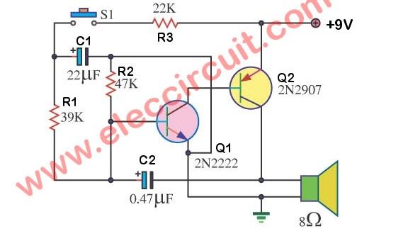
This whole circuit derives the power from a 9V battery which can comfortably cater to the power needs of modules or discrete components. The circuit will produce an up-down wailing sound from the speaker. The proposed project is divided into two parts the siren circuit and the rotating beacon light but before dive in to the details lets answer a very simple question.
This circuit produces a sound similar to the police siren. The two 555 act as an astable multivibrator. Open Proteus professionalexe and pick components from pick devices.
When the push button switch is pressed to 10u capacitor will charge via the 22k resistor. 3 Police Ambulance Fire Brigade Siren - USA Style. This circuit uses two NE 555 ICs and each of them wired as astable multivibrators.
The circuit uses two NE555 timers ICs and each of them are wired as astable multivibratorsThe circuit can be powered from anything between 6 to 15V DC and is fairly loudBy connecting an additional power amplifier at the. The circuit will produce an up-down wailing sound from the speaker. This circuit generates a tone that sounds very similar to a siren.
In the circuit diagram use IC1 in an astable multivibrator mode. Police Lights Themed Flashing LED Circuit Using 555 IC. Police Siren Circuit Explanation.
This circuit smoothly transitions the output sound between two different tonesfrequencies similar to the sound emitted from police cars. The output of this IC is connected to an 8-ohm speaker via a 47uf capacitor which creates a tone that resembles the sound exactly like a police siren. 12 volt NiCd battery charger design circuit diagram for your DIY.
We are going to make a Police Siren Circuit using two 555 timer IC. A lot of electronic circuits using NE555 timer IC are already published here and this is just another oneHere is the circuit diagram of a police siren based on NE55 timer IC. Diagnose each component value and connection.
The image of the designed circuit is given below. The circuit uses a UM3561 IC to generate a police ambulance or fire brigade siren. Place all the components on the screen as shown in upper picture and give them Specify values according to the picture.
With SW1 positioned as shown in the circuit diagram the typical dual-tone sound of Police or Fire-brigade cars is generated by the oscillation of IC1A and IC1B gates. Police siren generator circuit using 555 IC. Circuit Diagram of Police Siren Circuit using NE555 Timer.
Simple Police Siren Circuit Electronic Diagram Using 555 Timer American Police Car Siren By Ic 555 Under Repository Circuits 24421 Next Gr Star Trek Red Alert Siren Circuitdb. This is Electronic Siren circuit diagram which use standard discrete components. This circuit is intended for children fun and can be installed on bicycles battery powered cars and motorcycles but also on models and various games and toys.
This circuit consists of a breadboard two NE555 IC timers two potentiometers also called as presets LEDs buzzer and 9V battery for the circuit operation. It produces a low signal frequency comes out of pin 3 about 1 Hz. Note that you can also use a PNP transistor by connecting its emitter to pin 5 of IC 2 and collector to the ground.

Pin On Electronica
6 Simple Transistor Police Ambulance Siren Audio Alarm Circuits Circuit Diagram Transistors Circuit
Siriene Police Circuit Diagram Using Mtp3055v


Pin On Mini Projects