Detection system described in. Now connect jumpers between -ve terminal of the LED to collector pin of transistor and from the emitter of the transistor to -ve rail of Breadboard and from remaining LDR pin to ve rail of BreadBoard.

How To Make Ac Voltage Detector Using The Transistor Bc547 Electronics Circuit Electronic Circuit Projects Electronics Projects
Flame detector circuit using one transistor very sensitive and long range - YouTube.
Transistor Detector Circuit Using 1 Tr. REGENERATIVE DETECTOR A simple one-transistor REGENERATIVE DETECTOR circuit that uses the heterodyning principle for cw operation is shown in figure 3-4. Part of the standing collector current of Trl also flows through Tr2 from base to emitter thereby supplying the necessary bias. Negative feedback is provided by R5 and R3.
The article presents a comprehensive discussion regarding these tiny electronic devices in a very lucid style explaining BC547 datasheet their operating principle and how to implement BC547 and the associated. The circuit can be made to oscillate by increasing the amount of energy fed back to the tank circuit from the collector-output circuit by physically moving tickler coil L2. Neither of your circuits will work as intended.
Thais circuit uses only one transistor and can be transformed from negative to positive edge detector just by replacing position of switch. An Infrared Motion Detector circuit can be designed in different ways using different sort of components. Transistor BC547 is probably the most elementary of the available electronic active components and yet becomes the basic vital building block in most electronic circuits.
The circuit appeared here can be utilized to distinguish a wide band of RF signals and give a caution when it will detect an RF signal. The two transistors Q1 Q2 the two resistors R1 R2 and the capacitor C1 form an oscillator which only works when current reaches the base of transistor Q1. The same electronic projects can also be developed using the BC547 instead using the 2n2222 NPN transistor.
Best and simple Power Amplifier circuit diagram using 2N3055 NPN type power transistor. These two sets are ideal for those wishing to gain experience with transistors as they require no alignment. As this is out of phase with Trls base a high degree of stabilisation is achieved.
How the rain detector works. The current consumption of the circuit is very low being able to use 2 batteries of 15 V in series and thus obtain 3 volts. In this tutorial we are making a very simple project of an Infrared Detector Circuit which detects infrared light.
In this tutorial we have explained how to build a DIY Do It Yourself Infrared Motion Detector Circuit using 555 Timer IC IR Diode 2 comparator ICs and other associated components. It can be used wi. Hello guys in this video I will show u how to make a very sensitive flame detector circuit using one transistor.
As an example the following BJT configuration can be used as a switch for inverting an input signal for a computer logic circuit. CIRCUITS 1 AND 2 The two simplest types of transistor receiver possible are shown in circuits 1 and 2. Application of Light Sensor Circuit.
Finally connect a battery to the Breadboard and test the circuit. However utilizing these faulities positively we can constitute the useful circuits. The first is the closest but it triggers on the rising edge not the falling edge the on time is highly dependent on the specific transistors Vbe vs Ib curve and its h FEand it takes a long time to reset ready for the next trigger and also if the input is a 12V level like the supply when the input goes low it Zeners the ZTX689Bs reverse biassed B-E junction.
You can update the circuit at anytime you can replace the 2n2222 NPN transistors with the BC547 and it will have no negative effect on the project. The base bias for Tr 1 is taken from the collector of Tr2. This one is a low cost easy to build one designed using.
The entire power requirements are supplied by a single cell which may be either circuit. Transistor Detector circuit using 1 TR. So it really doesnt matter whether you want to use 2n2222 or BC547 NPN transistor.
Using just a single transistor and few zener diodes you can get different voltages ranging from 5 V to 10 V from a supply input of 12 V. PHOTOCURRENT AMPLIFIER CIRCUIT USING THE TRANSISTOR OF PHOTODIODE Figures 3 and 4 show photocurrent amplifiers using transistors. Some application are as below.
In the arrangement of Figure 3 A the photocurrent produced by the photodiode causes the transistor Tr 1 to decrease. The below shown diagram and the chart shows how the transistor the zener diode and the biasing resistor can be configured for implementing the simple transistor regulator circuit. An RF detector screens or tests the yield of an RF circuit and builds up a dc yield voltage relative to the power at that particular point.
Transistor Tester-1 Transistor Tester-2 Trickle Charger 12v Vehicle Detector loop Detector VHF Aerial Amplifier Voice Controlled Switch - see VOX Voltage Doubler Voltage Multipliers VOX - see The Transistor Amplifier eBook Voyager - FM Bug Wailing Siren Walkie Talkie Walkie Talkie with LM386 Walkie Talkie - 5 Tr - circuit 1 Walkie Talkie - 5 Tr- circuit 2. When this oscillator is active it reproduces a sound in the speaker. The circuit shown in Figure 3 are most basic combina-tions of a photodiode and an amplifying transistor.
A transistor switch is a circuit in which the collector of the transistor is switched ONOFF with relatively larger current in response to a correspondingly switching low current ONOFF signal at its base emitter. Transistor the variation of the several parameters with operating point bias voltage or current can be seen one of the faulity of it. Powerful Metal Detector Circuit Using TransistorWelcome to my channel Tech help here you will learn how to make diy electronics circuitshandmade craftsne.
Phototransistors exhibit the operation of both photodiodes and normal transistors. This circuit is using only three components an RS-276-145 phototransistor 330Ω resistor and a LED Light Emitting Diode.
![]()
Metal Detectors Circuit And Working Imaxgeek
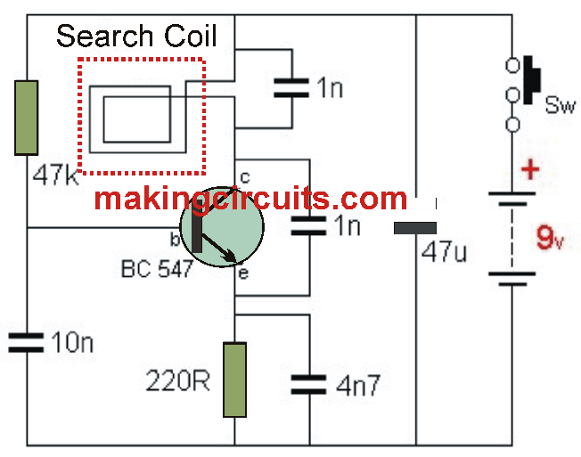
Metal Detector Circuit Using Single Transistor Tutorial
Basic Circuitry Of Metal Detection

Pin On گنجیاب