Dummy Alarm Circuit Principle. After the cut-off timer has switched the siren off - the buzzer will continue to sound.
26 Best Alarm Circuits Explained
Burglar alarm system is an important part of home security systems.
Burglar Alarm Circuits With Timer Delay. This 7555 timer is operated in astable mode to continuously and produces the waveform. With the exit delay set at 30-seconds - the siren will sound for about 15-minutes. Car Burglar Alarm using two 555 timers This is a simple Car Burglar Alarm circuit that uses a dual contact relay and two 555 timers each of them working as a monostable multivibrator.
Then it will switch off - and remain off. By Jayant Dec 12 2015 15. This burglar alarm project is based on PIR sensor UM3561 and Speaker.
This circuit is mainly used in homes and offices for security purpose. One to the fridge door edge and the other to the freezer door edge so that if either of doors were to be left open as much as 05 cm the alarm. Meanwhile the circuit is wired around a popular 555 timer IC.
Since the alarm that we present here uses no delay the only chance for the intruder to reach sensor cables would be due to wrong installation which may give access to cables at places that are not monitored by motion sensors. Building the Circuits Burglar Alarm 4-Zone Capacitor Charge Pump Car Lights Flasher warning flasher Car Tachometer Charge Pump Clark Zapper Clicks Uneven Calculator 555 7555 CMOS 555 Constant Current Continuity Tester Crossing Lights Curtain Closer Dark Detector Delay also called a Timer Delay before turn-on Dog-Bark Stopper. 555 Based Alarm Circuit.
The circuit consists of 7555 timer IC as main component. C1 could be greater or lowered in value to change the delay periods. 555 Timer Circuits Alarm Circuits Tagged Burglar Alarm Circuits This Keypad is suitable for the Modular Burglar Alarm.
Thus the system could be effectively use for detecting trespassing theft intrusion burglars or any form of. If that is correct please post a link or specifications for the IR receiver you are using state what your power source and voltage is going to be and post a link or specifications to the alarm you are using. I added an alarm to the 2 Relays of the circuits and I accommodated 2 Nos of push button switches on a piece of prototype PCB.
The PIR burglar alarm explained here will detect a human intruder within the stipulated range and sound an alarm. A drawer a closet a small room the car trunk etc. In this project if there is any obstacle in front of IR sensor it generates an interrupt signal.
You want to be able to turn the circuit on but have a 30 second delay before the IR detector can activate the alarm. This Time Delay Light switch circuit is useful to illuminate locations where a light source of low power is needed. Burglar alarm circuit or Theft alarm circuits are quite common and different circuits uses different methods to detect intruders.
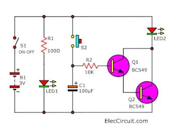
As I mentioned before I modified the 2 circuits according to your instructions to delay the start-up of the circuits for 90 seconds. And you want to use a NE555 IC in this arrangement. The main principle of the circuit is to flash an LED for every 5 seconds.
The burglar deterrent circuit is constructed using two monostables. P1 is used to set the time of delay between the bell being rung and the record being played to any value between 022 and 24 seconds. This burglar alarm is designed using 555 timer.
When activated the system provides alerts if and when intruders enter the residence as well as if and when a fire gas leak or other potentially dangerous conditions arise inside of it. However it has other applications. Examples of places to use this circuit are.
Burglar alarm Circuit using IC 555. Time Delay Light switch Circuit. The above circuit uses timer IC 555 to detect and sound alarm upon detecting intruders.
The refrigerator door alarm circuit uses two 555 timers Alarm using thermostats. Note- You can use one Variable Resistor instead of R3R4R5R6 but you need to previously check the timing Range. An ON Delay Timer Circuit is a simple electronic circuit which often serves to initiate time delays in different switching applications.
On Delay Timer Circuit using Three 2N3904 NPN Transistors. This output is applied to the high power LED which flashes. 555 IC Tester Circuit PCB 3.
This circuit convenients for to set up in an automobile. A voltage is obtainable with the time frame from the delay interval to keep the alarm circuit switched off. This delay of a few minutes or seconds at times becomes the deciding factor of the success of an industrial process.
4-Zone Burglar Alarm 1-10 Minute Auto Turn Off 5 Seconds Delay 10 Minute Timer - 74c14 12v DC to 12v DC Battery Charger 12v DC to 19v DC 12v to 240v Inverter 50 Duty Cycle 100dB Siren 170v Supply for Nixie Tubes 555s - a list of substitutes 5554017 Display 450 555 Amplifier 555 CMOS version LMC555 555 Kit of Components 555 Printed Circuit Board 555 Pinout. This is a low power IC of 555 series. Car Burglar Alarm timer alarm system circuit model to economize.
The alarm will activate the car horn approximately 5 seconds after either door. This circuit is designed to alert the user when an intruder enters into the home. Whereas P2 is used to set the time for which the relay remains activated for the external alarm.
Time delay circuit etc. Here is a simple and easy DIY project tutorial of a dark-activated alarm circuit utilizing a 555 timer IC. This circuit is ideal for small or temporary facility locations.
Car Burglar Alarm Timer Delay Using NE556. PIR sensor used to detect body motion and UM3561 speaker to produce Police siren after any movement detection. Turn ON this circuit by closing S1 Switch and choose the timer range by closing s3 s4 s5 or s6 switch then push the start switch s2 and wait the buzzer gives alarm sound depends on the timing range.
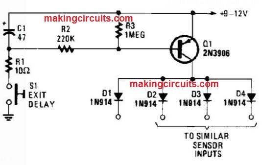
Switching on S1 charges C1 to the supply voltage. Yes this may happen but only if the sensor cables are accessible from places which are not supervised by motion sensors and also if the system uses time delay. PIR Burglar Alarm Circuit.
Usually switch at set up keep with automobile door will the circuit closes. This biases Q1 on through resistors R2 and R3. Of course - you can stop the noise at any time by switching off the alarm.
The Importance of Time Delay Relays in Burglar Alarm Systems Many homeowners install burglar alarms system in their homes to help keep their family members and possessions safe. The IC is likewise utilized as an Astable Multivibrator here. Generally it will deliver a perceptible alarm signal when there isnt any significant light on the surface of the LDR.
Exit Delay For Burglar Alarm Circuit. The siren cut-off delay is 30 times the length of the exit delay. A 555 -Timer Based Motorcycle Alarm.
Burglar Alarm Circuit.

9 Burglar Alarm Circuit Ideas Electronics Projects Circuits

Burglar Alarm Circuit Electronics Projects
10 Sec To 30 Min Time Delay Circuit With Relay Transistor Eleccircuit Com

Door Timer Circuit With Alarm