2 voltage pd across the lamp. Function remains the same as point.
How To Vary The Brightness Of An Led
So the brightness is a function of both.

Higher Brightness Variable Circuit. The third circuit will have the brightest bulb because adding resistors in parallel lowers the overall resistance in the circuit. Brightness of lamp power depends on two factors. To use that circuit get rid of M1 D3 and R2 and their Q1 is our Q2.
Putting this together A is the brightest bulb followed by E. In a parallel circuit 100W bulb glows brighter due to high power dissipation instead of an 80W bulb. This can be done with just a few lines of code in a micro-controller.
Take notes about the. This circuit that applies the output of 0-30V at 3A by using electronic components are bridge diode as main and control voltage by potentiometer easily. First of all obviously this is not true for all types of lamps because it says the brightness lumens of a lamp depends only on wattage.
A row of 12 displays 1 seven segment type x 12 2. If the resistors are very large they have no impact and the lamps will be the same brightness. Higher the duty cycle means higher the lamp brightness and lower the duty cycle means lower the lamp brightness.
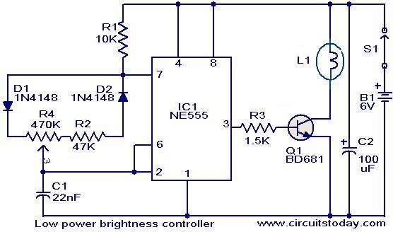
The entire circuit is build around timer IC NE555 IC 1 or we can also say IC 1 as heart of the circuit. Anything else will be something in between. The bulb which dissipates more power will glow brighter.
Mac users use the Command and the minus - key. More than that and it the bulb will probably get fused but less than that and it will definitely be less bright than what it co. Because the blue and orange currents add to the green current the blue current is 23 the value of the green current and the orange current is 13 the value of the green current.
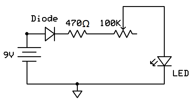
The light dimmer circuit or fan regulator circuit is used to control the brightness of the light or the speed of the fan according to our desire. When the potentiometer is turned all the way to the side where it has a resistance of near 0Ω the LED shines the brightest because the circuit has the least amount of resistance at this point so it produces the greatest amount of current which is fed into the LED. You blink it on and off rapidly 200 Hz is a good speed and change the ratio of on-time to off-time.
Dim the pixels when button A is pressed and brighten the pixels when button B. In a series circuit 80W bulb glows brighter due to high power dissipation instead of a 100W bulb. Connect the other end of led to ground in series with a resistance.
As you reduce the values to 250 100 75 50 and so on the blinking should become faster. Add an ammeter in the loop and a voltmeter in parallel with the bulb as shown in the first diagram. If the resistors are very small the brightness will be determined by the ratio of the resistors bigger one - brighter lamp.
This AC variable power supply project so may a good way for us. This is a number between 0 no light and 255 super bright. 1Current which flows through the lamp.
Bulbs B C D F and G are all the same brightness and the faintest. With the value of around 10 the LED appears to light up continuously. The cycling rate is variable from 03 to 3 flashes.
Set the brightness of all the pixels on the pixel ring. To change the brightness of your light you PWM it. See the bulbs brightness depends on the input power.
Change both of the values to 500 and write the program to check the LED status. Series and Parallel Circuits - Light Bulb Brightness - YouTube. The first circuit is the dimmest because it has no parallel branches and so offers the highest resistance.
Resistance can be in range of 120 ohm to 47 k ohm. A separate row of 3 displays 1 seven segment type x 3. If you need AC Power supply is cheaper this project is a good way.
Circuit Description of High Brightness LED Strobe Using IC 555. Set all the pixels to white. This is how the circuit works.
Use the Alt and the minus - key on Windows and Chromebook. Few arduino uno pins can be used to output variable voltage and pin9 is one of them. Use the Alt or Command key in combination with the plus key to increase the size.
Build a simple series circuit with one bulb and a battery. The higher the voltage v the higher the current. The objective of the circuit is to vary in intensity the brightness of the light bulb or fan speed by using a fixed source.
For example a 100-watt bulb will be giving an optimum performance when it gets 100-watt power. Make the circuit and upload the sketch in your ardunio uno. Duty cycle of the ICs output can be adjusted using the POT R3.
The blinking speed should increase. To do it using just a 555 chip try this circuit. You could increase or decrease the resistance in a circuit by using a variable resistor.
IC 1 is here used in astable mode and generate pulse. Answer 1 of 21. Circuit diagram of high-brightness LED strobe is shown in figure 1.
Make sure that if there is more than one voltage or current in a problem you use the voltage across the resistor and the current through it not just any values that you see in the question. A potentiometer with knob to control each display illumination individually so in all 12 pot knobs. The current is therefore greater and the bulb shines brighter.
If the brightness is caused by a flow of electrons through the filament a higher voltage will--all things being equal-- drive more electrons to flow through the filament. Click and drag the border of the breadboard toward the top of the canvas. Figure 16 shows a useful modification of the above circuit in which the flashing rate is made variable via RV1 and two pairs of series-connected LEDs are connected in the form of a cross so that the visual display alternately switches between a horizontal bar LED1 and LED2 ON and a vertical bar LED3 and LED4 ON thus forming a visually interesting display.
It outputs analog values in the form of pwmpulse width modulated signal. This case depends on the ratio of the resistors to the resistance of the lamp. The new brightness of all the pixels in the ring.
Diode D1 by-passes the lower half of the POT R3 during the charging cycle of the astable multivibrator. There is no need to replace the bulb with a higher. Resistors R1R2 POT R3 and capacitor C1 are the timing components.
Each knob increases or decreases the intensity value from 0 to 9 for its individual display.

Led Brightness Control Circuit

Led Brightness Adjustment Circuit Download Scientific Diagram
Brightness Controller For Low Power Lamps

Led Display Brightness Controller Circuit