The TDA8950 is available in both HSOP24 and DBS23P power packages. IC1LM386 Low voltage audio amplifier SP18Ω 025W.

Lm391 Guitar Amplifier Circuit
The LM391 is internally protected for output faults and thermal overloads.

Audio Amplifier Pcb Lm391. Since TO 204 sheath power transistors are used cooler pcb assembly etc. 200W Audio Amp Please watch complete video on YouTube before making. Using an 8Ω load and 30V supplies over 30 watts of power may be delivered.
Here the 35W power audio amplifier circuit based on LM391. Digital Scale PCB For complete tutorial watch my YouTube video. Inductor L1 is constituted by 20 coils of wire with thickness 09mm round resistor R16.
The transistors Q3-4 are the final amplification section it should be placed on heatsink. 20 Audio Amplifier PCB This is a cool 20 stereo Audio Amplifier Circuit You can easily build. 40 Watt Amplifier using IC LM391.
This circuit scheme is an audio amplifier that can produce 35 Watt output with small distortion. High power supply voltage operation and true high fidelity performance distinguish this IC. 100W Basic MOSFET Amplifier Circuit.
Marshal Power Amplifier Hi-Fi PCB Layout Only. Audio Board Amplifier Cars 2 Channel 1 Volume Handle Electronic PCB Circuits 15W. The amplifier is designed to operate with a minimum of.
Water level indicator Water level indicator tutorial. 100 Watt Hi-Fi MOSFET Power Amplifier Circuit. 2N6609 2N3773 HiFi Amplifier Circuit 550W.
Here the 35W power audio amplifier circuit based on LM391. The advantages of this IC is its easy use and only needed some additional components only. Its advantage is small easy to crease cheap and without any modifications.
Electronic Amplifier Circuit Board Pcb Maker 2000w Audio Amplifier. C 1500 25 off. It is a very good design to assemble easy to build from your board to the acquisition of components the output transistors are the COMPLEMENTAR 2SC5200 and 2SA1943 relatively cheap and with very good result.
If are used the Q3-4 in packing TIPxxxx they can be placed straight above in PCB. If are used the Q3-4 in packing TIPxxxx they can be placed straight above in PCB Read More. The transistors Q3-4 are the final amplification section it should be placed on heatsink.
T22 and T23 take current measurements over 047-ohm resistor and take the T11 and T12 to the cut and go to protection. For Details watch my youtu. The LM391 is internally pro-tected for output faults and thermal overloads.
Digital Petrol Pump machine Here is the Video tutorial link for this project. This is the circuit diagram of a 35W audio amplifier based on LM391. The LM391 is a comprehensive driver to the power transistors.
Stereo Power Audio Amplifier With Tda7297 2 X 15 Watts Xtronic Org. The core of this circuit is LM391 type IC. Inductor L1 consists of 20 turns of wire thickness of 09mm around the resistor R16.
One end will connected to this circuit and one to the audio source like mobile laptop etc. C1 C201μF 50V Ceramic C3C410μF 25V Electrolytic C5220μF 16V Electrolytic. A challenging but high quality design.
At the output end of this circuit you can either use simple Headphoneearphones or can use Subwoofer or speaker. The transistors Q3-4 are the final amplification section it should be placed on heatsink. Inductor L1 is constituted by 20 coils of wire with thickness 09mm round resistor R16.
TDA2030 Bridge Amplifier Circuit with PCB. Lm386 Based Audio Amplifier Full Project With Circuit Available. Building of the amplifier on the PCB must be easy.
The amplifier operates over a wide supply voltage range from 125 V to 40 V and features low. The amplifier has Output short-circuit protection. For giving audio input to this HeadphoneAudio Amplifier Circuit user need to use AUX cable which has 35mm audio jack at both the side.
This is the circuit design of 1000W stereo audio amplifier. Inductor L1 is constituted by 20 coils of wire with thickness 09mm round resistor R16. Pcb Layout Equlizer 5 Channel Rangkaian Elektronik Desain Tata.
This requires a - 15V Dual Power supply at the current least of 2A. High power supply voltage operation and true high fidelity performance distinguish this IC. Here the 35W power audio amplifier circuit based on LM391.
35W Audio Amplifier Circuit based LM391 IC. The IC LM2876 is a high-grade audio amplifier chip which is designed to continuously handle 40 watts of average power over an 8 Ohm loudspeaker with a THD of 01 and a. The typical output power is 2 150 W with a speaker load impedance of 4 Ω.
The LM391 audio power driver is designed to drive external power transistors in 10 to 100 watt power amplifier designs. Portable Headphone Amplifier Circuit. It needs only few external components to work.
Balanced Microphone Preamp Circuit. Circuitry providing output transistor protection is user. In the power supply module we have 6.
555 Circuits 10 Alarm Circuits 3. This is the FM transmitter circuit which apply 4 radio frequency stages that are a VHF oscillator designed around transistor BF494 T1 a preamplifier designed around transistor BF200 T2 a driver designed around transistor 2N2219 T3 and also a power amplifier. LM391 IC is a driver devoted to driving the transistor-based amplifier.
The LM391 audio power driver is designed to drive external power transistors in 10 to 100-watt power amplifier designs. Figure 2 the PCB and components layout of the LM386 audio amplifier. Lm1875 Audio Amplifier 20w.
Because we use two TDA2030. The TDA8950 is a high-efficiency Class D audio power amplifier. 5 R110Ω R212K VR110K Potentiometer.
The LM1875 is a monolithic power amplifier offering very low distortion and high quality performance for consumer audio applications. 35W Audio Amplifier based LM391. TDA8950 g eneral description.
Amplifier Circuit January 18 2017. LM391 an audio power driver designed to drive external power transistors in 10 to 100 watt power amplifier designs with features such as high power supply voltage operation low distortion dual slope SOA protection internally protected for output faults and thermal loads true high fidelity performance low input noise shutdown pin high. The supply voltage might range between 12 V and an absolute maximum of 44 V.
With the TR1 we can adjust the bias current to 45mA. The LM1875 delivers 20 watts into a 4Ω or 8Ω load on 25V supplies. It gives an output power of 35 watts to 40 watts at 8 ohms speaker.
Audio Amplifier Pcb Lm391

35w Audio Amplifier Circuit Based Lm391 Ic Circuitszone Com
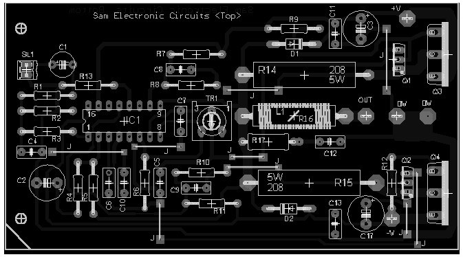
35w Audio Power Amplifier Circuit Based Lm391 Top Pcb Layout Circuitszone Com

35w Audio Amplifier Based Lm391 Amplifier Circuit Design