This can be set through P2. For best performance it can be teamed with the Stereo.
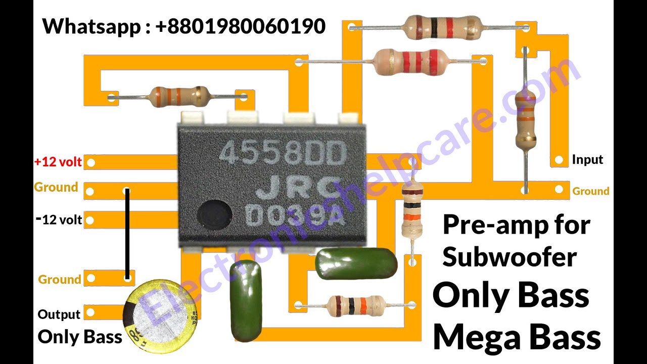
This Is A Subwoofer Circuit Diagram It Also Call Low Pass Filter For Making Subwoofer We Have To Use This Circuit Diagram Subwoofer Electrical Circuit Diagram
The TRRS audio plug is found on iPhone headphones and other headphones that have a microphone.

Stereo Headphone Circuit Diagram. For example in case a module will be powered up and it sends out the signal of half the voltage in addition to the technician does not know this hed think he provides an. The values shown in the circuit gives a gain of 11. Dynaco Dynakit Mark IV Tube Amplifier Schematic - 40 Watts PP class-AB NEW.
The receiver can be powered by using a 9V battery. The LM4809 is known as a stereo audio power amplifier capable of delivering 105mW per channel of. Use a power supply rated at 350 mA.
This HiFi headphone amplifier circuit design is normally used to drive a headphone with a relative low impedance. After you cut open the plastic insulating sheath youll find 5 separate wires. Headphone Amplifier Main Features.
Class A Headphone Amplifier Circuit Diagram 62074. Heres a top-class headphone amplifier that can drive high or low impedance phones to full power levels with very low noise and distortion. How to build Stereo Headphone Amplifier Circuit Schematic August 5 2010 - category.
Bass treble tone control circuit using opamp. Operating voltage installed on circuit OPA2134 opamp symmetrical -15v dc. Main View Of Stereo Headphone Amplifier Circuit Diagram.
This circuit is made in such a way that user can not only use it as Headphone Amplifier but also can drive a subwoofer speaker or normal speaker 4 ohms and can get a amazingly loud sound through the speaker. Up to 8Ω and 32Ω. Simple bass treble tone control circuit diagram.
To switch it between these two modes we have used three jumpers here. Parts Layout Of Stereo Headphone Amplifier Circuit Diagram. The memory block bluetooth voltage interface microphone and he.
Stereo Headphone Amplifier Swc Electronics Lab Njm386 Headphone Amplifier Hifi Headphone Amplifier Circuit Using Tl072 Low Noise Elec Circuit. The voltage at the junction of R13 and R14 must be set at 50 of the power supply. Picture of the circuit.
The photo transistor T3 receives the IR signals. The collector of IR is connected to base of T4 BC548 which amplifies the signal together with T5 BC549to regain the audio signal transmitted. The standby current through the final transistors is about 50.
Ptb passive treble bass circuit wiring diagram. Credit for this circuit goes to SiliconChip. The transistor T6 drives the headphone to reproduce the sound.
But it does not imply connection between the wires. Sound Cmoy Mic Vacuum Tube Headphone Amplifier Schematic Amplifier Bc547 Transistor Stereo Headphone Amp Am Receiver Circuit Low Noise Microphone Preamplifier Headphone Jack Condenser Microphone Splitter Amplifier Circuit 35 Mm Mic Preamp. Once youve identified the wires simply solder them to the correct input channels in your circuit or attach pin connectors so they can be used in a breadboard.
Hi fi stereo headphone amplifier circuit. Circuit diagram with Parts list. Dynaco Dynakit Stereo 35 ST35 Tube Amplifier Schematic - 175 Watts PP class-AB Dynaco Dynakit Stereo 70 ST70 Tube Amplifier Schematic - 35 Watts PP class-AB Dynaco Dynakit Mark III Tube Amplifier Schematic - 60 Watts PP class-AB NEW.
NuHybrid headphone amp - A low-voltage hybrid headphone amp using the Korg Nutube 6P1 __ Designed by Pete Millett. Firstly Id like to stress that the intended use of this circuit is only one of many possible applications. 4558 ic bass treble circuit diagram.
The Studio series is a premium stereo headphone amplifier with very low noise and distortion. Studio Series Stereo Headphone Amplifier A top-class unit for the audio enthusiast. Occasionally the wires will cross.
This diy headphone amp circuit will increase the here is a schematic diagram of a diy headphone amp circuit which will increase or amplify the audio in. Headphone amplifier circuit diagram. 14 Headphone Circuit Diagram.
R3 is the feed back resistor for left channel while R4 is the feed back resistor for the right channel. High performance very low noise and distortion Can be used with high and low impedance headphones High output power 200mW. The headphone amplifier delivers an output of around 1 watt.
Injunction of 2 wires is usually indicated by black dot at the intersection of 2 lines. Rate this link QRV-04 - The high performance SMD headphone amplifier - Cute SMD headphone amp designed especially for OPA134 OPA627 and AD8610 plus a buffer BUF634. According to earlier the traces at a Stereo Headphone Jack Wiring Diagram represents wires.
6 Steps Stereo Headphone Jack Wiring Diagram In addition Wiring Diagram provides you with the time frame by which the assignments are to be completed. Mapletree Audio Designs MAD Ear Stereo Headphone Amplifier Kit - This tube headphone amplifier kit manual has building instructions and full circuit diagram of this device. This may result in distortion around the crossover region where one transistor turns off and the other on.
R1 and R2 are the respective input resistors. Circuit diagram of the LM4910 stereo headphone amplifier is shown aboveC1 and C2 are the input DC decoupling capacitors for the left and right input channels. This more than doubles the battery life compared to just connecting a simple resistor.
Multimedia hi-fi power amplifier circuit. You will be in a position to understand specifically once the assignments ought to be accomplished that makes it much easier to suit your needs to effectively handle your time. It provides one watt power output and it can also be applied as an output stage for preamplifiers in conjuction with active loudspeakers boxes.
Simple Headphone Circuit Diagram. The headphone amp is composed of an OP-AMP and an additional transistor amplifier. Otherwise the arrangement will not function as it should be.
Stereo headphone amplifier LM4910. The amplifier gain is dependent of the resistors R4 and R6. This circuit can be used for stereo headphone amplifier circuit for home audio system microphone preamplifier personal computers and PDA headphone amplifier and more.
1w Stereo Headphone Amplifier Based Tda2822 Electronic Schematic Diagram The Class A Amplifier Site Jlh Headphone Amplifiers Hi Fi Headphone Amplifier Circuit Diagram Under Repository Circuits 20783 Next Gr. 15V Headphone Amplifier - This circuit stabilizes the quiescent voltage across the speaker at the exact level necessary to get the desired maximum available volume at minimum battery draw. Circuit diagram of the LM4910 stereo headphone amplifier is shown aboveC1 and C2 are the input DC decoupling capacitors for the left and right input channels.
Diagram hi fi dx bass circuit diagram full version hd quality circuit diagram. Apart from the obvious usage as a headphone amplifier the circuit can be used for a range of applications where a wide. This is the stereo headphone amplifier circuit diagram built based LM4809.
Bass treble board volume bass treble mid control board. To properly read a electrical wiring diagram one offers to learn how the components inside the system operate. Make Music Controlled Christmas Lights.
Headphone Jack Wiring Diagram 35mm headphone jack wiring diagram bose headphone jack wiring diagram female headphone jack wiring diagram Every electric arrangement is made up of various diverse pieces. This Headphone Amplifier Circuit is made by using LM386 Audio Amplifier IC. Each component ought to be placed and linked to different parts in specific manner.
R1 and R2 are the respective input resistors. R3 is the feed back resistor for left channel while R4 is the feed back resistor for the right channel.
2sc5200 2sa1943 Amplifier Circuit Diagram Pcb Amplificador De Audio Amplificador De Som Caseiro Esquemas Eletronicos

3 Phase Electrical Switchboard Wiring Diagram And Phase Wiring Installation In House Electrical Wiring Diagram Electrical Wiring Electrical Circuit Diagram

Pin On Bateria

Wiring Diagram For House With Mcb Rating Selection Guide Etechnog In 2021 Electrical Wiring Diagram Electrical Circuit Diagram House Wiring