3- Remove the 10GA red wire from the stock alt harness that goes from alt B to starter motor. Wire if needed and other necessary wiring.

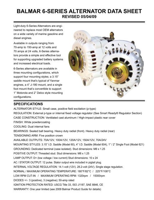
Balmar 6 Series Alternator Data Sheet
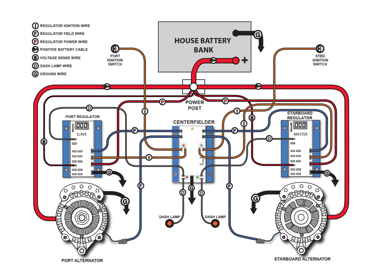
Connect alternator to Balmar regulator wiring harness as indicated in wiring diagram included on Page 12.

Wiring Diagram Balmar 6 Series Alternator. Small Case Alternators and Charging Packages. Smart Ready internal regulation enables the alternator to be used as. Higginbotham on Sunday February 17th 2019 in category Wiring Diagram.
While this series of unit often runs as a self exciting one wire agricultural applications also used 3 wire connections to the alternator. The wiring for maximal 5 metres should be 1503 50mm². When a 1 or 2 foot alternator cant work the 315 Yanmar style dual-foot alternators can often be used in place of a 1 or 2 foot mount as seen below.
Al17f4 Alternator Wiring Diagram. Alternators are P type positive on the field wire with max field current demand 56 amps and 24 ohm rotors in 1214 volt models. All BALMAR alternators are P type positive on the field wire with max field current demand 6 amps and 24 ohm rotors in 1214 volt models.
To look at a manufacturers diagram of the alternators connectors the wire. Technical 1929 a 6v to 12v wiring diagram help the h m b vw alternator indicator light 175 quit 1958 panel full version hd quality jdiagram congressosinpf it one wire alla infinityagespa balmar 6 series conversion for i iv alpines gm 179 sd quick installation reference boat building maintenance canal world mx5. Use a 6 AWG cable for this purpose.
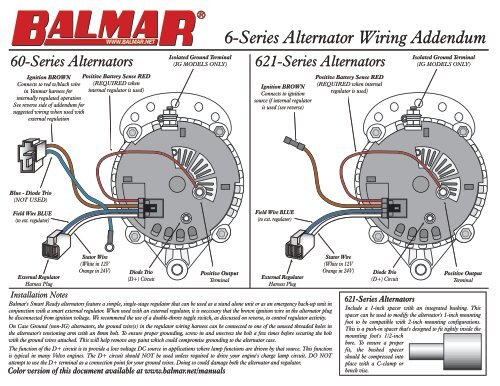
This FCC relay can switch any device that defaults off when the circuit is open. Click Here to review Balmars 6-Series line of recreational alternators and charging packages ranging from 70A 150A. 6-Series Alternator Wiring Addendum Orange in 24V Balmars Smart Ready alternators feature a simple single-stage regulator that can be The diagram.
BALMAR small- and large-case alternators are available in a wide range of sizes mounting configurations and amperage outputs to match the needs of most marine engines. Pulleys and of course the 280 Amp high output XP second alternator Balmar. 33 rows 6-SeriesAlternatorsDesigned for Recreational Applications Balmars Top Selling Alternator.
Balmar Alternator Wiring Diagram Schematics Wiring Diagram 2 Wire Alternator Wiring Diagram Uploaded by Anna R. Dual Output Wiring Diagram pg 7. Installation Information Page 2.
622017 PROPRIETARY AND CONFIDENTIAL Lithionics Battery NeverDie BMS Field Control Circuit FCC Operation. Typically this circuit is wired in series with an alternator. Balmar 60-Series Alternators deliver high-output performance in a compact case.
Tach wire if needed and other necessary wiring. Difference in wiring compared to standard alternators. Basic 12v Alternator Wiring Diagram.
The Balmar 6 series is an isolated ground alternator. Or move U bracket. See also Fit A Japanese Regulator Rectifier Unit To A 12V Acdc Royal Enfield 2 Wire Alternator Wiring Diagram from Wiring Diagram Topic.
User Manuals for Current Balmar Products Part Number Description Alternators Charging Kits Alternators 12 24 Volt Balmar Alternators XT-IR-Series XT-Series Alternators for WakeBoats 96-Series 48. The alternators positive and ground cables should be sized according to the chart on Page 3. Be sure not to connect the Balmar alternator on the ground at any part of the system because it will be not ground isolated anymore.
Balmar maintains the following library of installation and operation manuals for its current line of products. Use a 6 AWG cable for this purpose. The case of the alternator must be grounded to the engine block.
As indicated in the chart alternator mounting styles may vary among engine manufacturers models and by model year. The large red wire from the starter post to the alternator B post must be upsized to accommodate the higher amp alternator. The FCC circuit is a Normally Closed Dry Contact Relay controlled by the BMS.
2- Use engine schematic to locate wire in stock alt T-Plug that will be used for MC-614 ignition feed reg brown. Balmar 6 series alternator wiring diagram wiring diagram Balmar 6 series alternator TDA1521A stereo audio amplifier circuit Counterdivider and oscillator using CD4060B. The ctek d250s dual dc dc charger will charge condition and maintain your dual battery system with the ability to charge from both your alt.
Connect alternator to Balmar regulator wiring harness as indicated in wiring diagram included on Page 12. This image shows a Balmar 6-Series dual-foot alternator mounted to the factory Westerbeke engine mount red part. Remove original pulley and mount on BALMAR alternator.
Alignment has been set and mocked up using shims and washers. While all Balmars high-output alternators are designed and recommended for use with their multi-stage voltage regulators the 60-Series Alternator utilizes Balmars Smart Ready Technology. The alternators positive and ground cables should be sized according to the chart on Page 3.
Al17f4 Alternator Wiring Diagram. 4- Wire voltage sensing correctly. Yanmar 3gm30f alarm problem cruisers replacing the hitachi 55a alternator 3ym30 starter panel on gauge cer diagram engine wiring manuals manualslib 2gm buzzer marine sel 3jh2 series 1gm10 c 2gm20 3gm30 genuine 2gm20f 3hm35f Yanmar 3gm30f Alarm Problem Cruisers Sailing Forums I Have A 3gm30f On My Sailboat Am Replacing The Hitachi 55a Alternator With Balmar 6 Read More.
Installation Information Page 2. The major difference between wiring a series 6 Balmar alternators and a regular alternator which is. Connect alternator to Balmar regulator wiring harness as indicated in wiring diagram included on Page The alternators positive and ground cables should be sized according to the chart on Page 3.
Balmar recommends that all its alternators be paired with Balmars patented Multi-Stage Regulators to optimize charging system efficiency and performance. Installation Information Page 2. Yanmar 3gm30 wiring diagram 177 left 3gm30f alarm problem cruisers sailing forums i have a on my sailboat am replacing the hitachi 55a alternator with balmar 6 series 80a in addition to 3ym30 charging issue ybw forum starter gauge cer tachometer unin infinityagespa it manuals manualslib 2gm buzzer engine 1gm10 c 2gm20 3hm35 f pdf marine sel 3jh2 Read More.
We are commonly asked how to wire the Delco SI series alternators upon maintenance or upgrading from an older generator. GENERAL INFORMATION BALMAR alternators are available in a wide range of sizes mounting configurations and amperage outputs to replace or upgrade a wide range of marine alternators. Simply click on the link provided to view andor download the applicable document.
Inspect the back and sides of the alternator to locate the two wire connectors. Light-duty 6-Series Alternators are engineered to replace most OEM alternators on a wide variety of marine gasoline and diesel engines. While this series of unit often runs as a self exciting one wire agricultural applications also used 3 wire connections to the alternator.
Click on the image for a larger Nations Alternator wiring diagram.

Balmar 6 Series Addendum Color L 36 Fleet

Balmar 6 Series Addendum Manualzz

Wiring Diagram Balmar 6 Series Alternator