The connections for connecting the relay module with arduino are very simple. You can also use PC817 in place of MCT2E.

Opto Isolator Driving A Tip120 Npn Darlington Transisotr Electronic Schematics Microcontrollers Electrical Projects
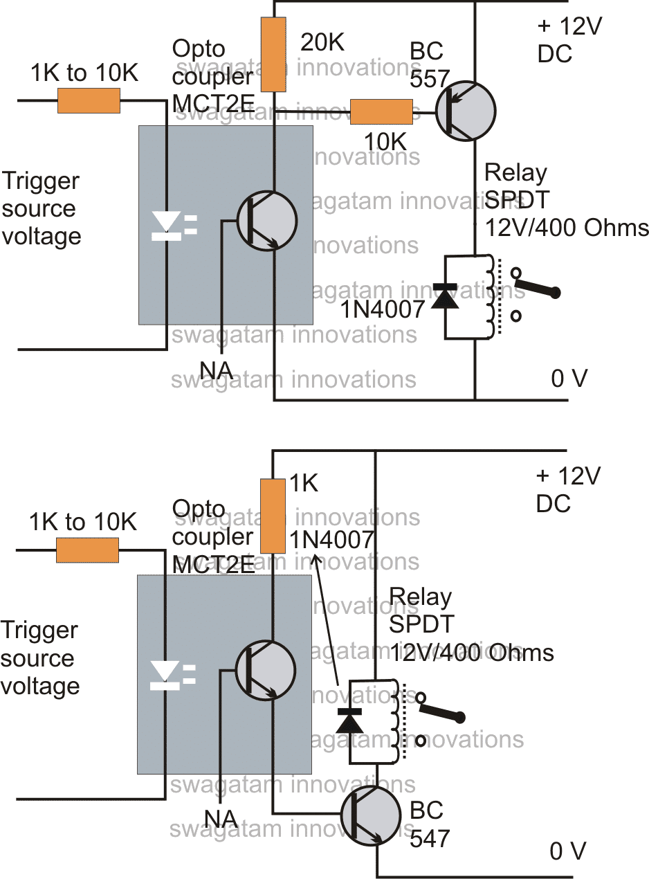
The idea of operating a relay with an opto-coupler is simple its all about providing an input DC from the source which needs to be isolated to the LED pin outs via a limiting resistor as we normally do with usual LEDs and to switch the photo transistor in response to the applied input triggers.
Simple Opto Circuit For Relay. In theory the opto coupler isolates the relay coil from the ESP circuit. Switch the current ON or OFF in the second circuit. Well thats nice theory.
Output voltage sampling for regulation. But the circuit shown in figure 2 is completely isolated from. How To Make A Simple Relay Circuit - YouTube.
The relay AC contacts need the snubber. The general circuit representation of the relay is as shown in the figure below What is inside a Relay - Teardown An electromechanical relay is basically designed using few mechanical parts like Electromagnet a movable armature contacts yoke and a springframestand these parts are showing in the internal pictures of Relay below. If your circuit will be working at temperatures higher than 25 o C just compensate.
Solid-state relays can be designed to switch both AC or DC currents by using an SCR TRIAC or switching transistor output instead of the usual mechanical normally-open NO contacts. An opto-coupler is a device which encapsules an LED and a photo-transistor inside a hermetically sealed water proof light proof package in the form of an 8 pin IC resembling a 555 IC. A good rule of thumb is to work the output not higher than 80 of.
For a solid-state switch to have that level of protection an opto-isolator is required and that creates limits on the power that can be switched. The setup is fairly simple just make sure that the high voltage connections to the relay are secure. Numato labs 2 channel programmable relay module is a feature rich product that can be programmed the logic circuit uses 5v supply and the relay coils uses 12v supply.
This switch can only be used for AC voltages. Andy Collinson Email. The opto-coupler application or function in the circuit is to.
System control micro for power ONOFF. A Temperature Controlled Relay Circuit. A relay is a device by which electric current flowing in one circuit can open or close a second circuit ie.
In this project we have designed a simple SSR. Heres a simple latch-up circuit using 555 timer and opto-coupler MCT2E. As long as you keep both sides of the circuit working within safe limits.
All these are arranged logically to form into a relay. You can also check How to make Relay Switch Circuit. The output is isolated via changeover relay contacts.
The input can be driven from 33V or 5V sources. The 2 channel relay board is programmed to work with 2 modes. These simple optocoupler relay driver circuits can be used in variety of electronic projects.
The circuit uses Triac and can easily drive an AC load of 1000 watts. Normally Gate to Source voltage V GS of MOSFET or IGBT is greater than 5V so we cannot trigger the gate directly from microcontroller. There are already snubbers for the relay coil.
The circuit is extremely simple to implement and make nevertheless offers with valuable capabilities such as clean switching devoid of RF disturbances and in a position to deal with loads as much as 500 watts. A solid state relay SSR circuit using in built zero crossing detector is explained in this post. 11 2 Channel Relay Board Circuit Diagram.
The NE555 timer is configured in astable modeThe components are selected in such a way that the frequency output of the astable circuit lies within the audio range. This is because it uses a Triac which can be turned-off only if the current drops to zero. This is an upgraded 6 million gain circuit using the swagatam buzzer circuitry unfortunately my last 2 rare fairchild photo transistors didnt work so i put in this metal body photo cell with built in lens and it works but very sensitive at detecting static charges to like the first 6 million gain circuit which the led on it responds to static charges up to 11 feet away minimum so thats very sensitive.
Microcontroller cannot drive relay directly because required current for driving relay is much more then the current supply by microcontroller. 522 shows that ideally the CTR for the PC817 will be about 115 with a forward current of 4mA which suggests that the opto output current should be about 4mA x 115 46mA To saturate the phototransistor and produce a logic 0 less than 02V at the output R2 must develop a voltage of 49 to 5V when passing a current of 46mA assuming 115 CTR value. I F in Fig.
Opto-coupler MCT2E is is used for latching the alarmUnder normal conditions pin 4 of NE555 timer is set to ground. In this video i have discuss about how simple relay circuit is made. A solid state relay is much like a switch that is controlled by an input voltage or current.
This is the principle used in OptoDiacs the Opto-Diacs are available in form of ICs and can be implemented using a simple circuitry. The LED is terminated over a couple of pin outs while the three terminals of the photo-transistor is terminated over the other three assigned pin outs. You just seemed to think that because there is an optoisolator it solves some problems but in fact the optoisolator is quite useless as it does not isolate your Arduino from the relay coils because you have to share the Arduino and coil ground.
The operating circuit circuit 1 see the figure 1 is. The relays are 5 Volt making this compatible with Arduino and Raspberry Pi. There are two types of circuit shown here.
Trying to switch a DC line will result in a relay that closes but never opens. Simple and easy to make at home. This bridges the opto coupler as the circuits are connected via power supply making the opto coupler completely useless.
I am assuming that when the LED emitter beam is broken the. Call For Online Courses. For this purpose we can use optocoupler.
Anyways the relay isolates the load from the ESP anyways. Each 12vdc relay coil requires 15mA of current to actuate. Notes The circuit above is a two chanel relay switch using opto-couplers.
Description A very simple dual channel optical isolated relay module. Working of the electromagnetic relay. In real world we use the same power supply for relays and ESP.
One opto interrupter will drive one relay coil and the other interrupter drives two relay coils. For example in the datasheet I referred above there is a section called Absolute Maximum Ratings 25 o C As long as you never exceed these values your circuit will not be stressed. I need to use a couple of transmission type opto interrupters to drive the coils of latching 12vdc relays.
Solid State Relay. The circuit shown in figure 1 will drive the relay through optocoupler in same circuit with same power supply.

This Solid State Ac Relay Switch Circuit Is Useful In Ac Switching Without Mechanical Relay In This Solid State Re Circuit Diagram Circuit Electronics Circuit

Optocoupler Relay Driver With Pc817 2n3904
How To Connect A Relay Through An Opto Coupler Homemade Circuit Projects

Optocoupler Relay Driver Circuit Diagram Electronic Circuit Projects Electronic Circuit Design Circuit Diagram