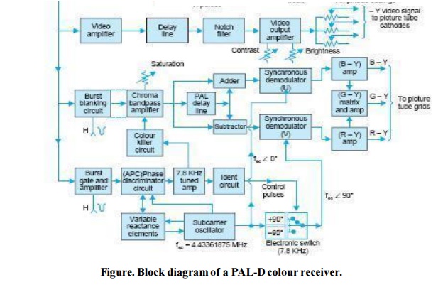
Values were based on you using an LED with a 26 voltage drop. Chroma decoder The main function of chroma decoder is to recover U and V colour difference signals which are combined with Y to obtain RG and B video signal For this the decoder has to perform following functions Chroma signal seperation and amplification Separation of U and V Demodulation of U and V Generation of subcarriers for two demodulators To develop ident signal.
Electronic Color Code Resistor Diagram Png 1024x576px Electronic Color Code Brand Chart Circuit Diagram Code Download
If you are not sure feel free to ask.
Colour Decoder Circuit. Electronic Circuit Schematics Note that all these links are external and we cannot provide support on the circuits or offer any guarantees to their accuracy. Given a binary code of n-bits a decoder will tell which code is this out of the 2n possible codes. Decoding color of the bands into resistance value it is answer on what the resistance with the colors brown-black-red-gold and the like.
PAL decoder provides RGB signals. CCVS signal is available at the video detectors output. To use this tool simply click on a particular color and number and watch how the actual bands on the resistor illustration change.
Our antivirus analysis shows that this download is safe. Decoding the Resistor Colour Codes 101. The most popular versions among the software users are 18 and 16.
Colour picture tube required for this section is totally different from the monochrome picture tube. Deflection circuits for colour receiver are similar to that in a monochrome system except that additional currents for removing pincushion effect are made available for the deflection yoke. With these color bands we can identify the resistive value and its percentage tolerance of a resistor.
Decoder circuit arrangement for decoding binary coded colour video signals to produce analogue colour video signals therefrom comprising three inputs 123 to which the binary signals are applied these inputs being connected through an analogue level conversion circuit 5 to a selector circuit 6 both of which are provided in an 8-channel analogue multiplexer demultiplexer 4 the. Some circuits would be illegal to operate in most countries and others are dangerous to construct and should not be attempted by the inexperienced. To connect to this function use the white NEGATIVE wire and the Blue POSITIVE wire.
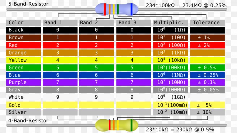
Our Resistor Color Code Calculator is a handy tool for reading carbon-composition resistors whether its a 4-band 5-band or 6-band type. Here are some resistor values using LEDs either on the output of a signalling circuit or a decoder. The common filenames for the programs installer are RCCD-v16exe or RCCD-v17exe etc.
Resistor Colourcode Decoder belongs to Photo Graphics Tools. Resistance color code decoder function. Continued WHITE WIRE this is usually termed either Function 1 FL or front light.
Select a number of color bands choose a color to each of them. Thus a decoder has n-inputs and 2n outputs. When the resistor body surface is large enough as in large wattage resistors the resistance value tolerance and wattage are usually printed on the body of the resistor.
PAL Decoder Color Processing section. All 5-band resistors use a colored tolerance band. Colour decoder circuit diagram - UV decoder To demodulate the U signal the chroma signal is fed via the analogue switch 4053 for the first 180 degrees of the in-phase subcarrier SC clock U to the non-inverting input of the op-amp and for the remainder to the inverting input.
Decoder is a combinational circuit that decodes the data from n input lines to 2n outputs. The NMRA recommended practices that define the colors and functions of the wires attached to locomotive decoders. Switch and contact position may also vary with time due to product evolution so check carefully when using them.
Chroma signal propagated slowly in the colour decoder circuit due to lower bandwidth and hence Y signal has to be delayed. Where circuits and wiring are shown these have also been checked or tested however case-by-case it is possible that exact wire positions may vary with orientation of things like turnout motors. It goes to the video pre-amplifier which amplifies the CCVS signal.
Where R- Red G-Green B-Blue. All these resistors can be 14 watt. Wires may be color-coded to identify their function voltage class polarity phase or to identify the circuit in which they are used.
The colors brown red green blue and violet are used as tolerance codes on 5-band resistors only. The insulation of the wire may be solidly colored or where more combinations are needed one or two tracer stripes may be added. So when you follow my diagrams below.
RED WIRE this is to pick up power from the track. It consist of colour demodulator which provides demodulated U and V signals. These color bands indicate the values of those resistors like the identity card does for us.
This free program is a product of Michael Barron. Oct 30 The 8 Pin DCC Plug is one of the standard plugs used for of a loose wiring harness coming from the decoder and mates with a fixed 8 hole. How your decoder controls this wire will be clearly stated in the instructions but it is usually set at the.
The blank 20 band is only used with the 4-band code 3 colored bands a blank band. A look into the electronic circuit board mostly shows wires with colorful bands called resistors. Which are applied to picture tube and PAL decoder also consist of ACC Automatic ColourControl and colour killer circuit.
Color-coding is also used for capacitors inductors and diodes. Here if three inputs are available in the decoder eight outputs will be available in the decoder which is known as 3-to-8 decoder. Ideally the Decoder circuit was made to decode the encoded information and here as its name indicates a decoder is a circuit component that decodes an input code.
Standard resistor values shown in parentheses. You can probably use the first standard value in parentheses. Figure shows the blocks of 2-to-4 3-to-8 and 4-to-16 decoders.
Decoder wiring colour codes and what the wires all do.

Pal Decoder Diagnostics Radios Tv
Pal D Colour Receiver

Wiring Color Codes For Dc Circuits Band Resistor Color Code Diagrama De Circuito Electrico Resistores Esquemas Eletronicos

Electronic Color Code Resistor Wiring Diagram Electronic Component Png Clipart Angle Area Chart Circuit Diagram Color