The small base current controls the larger collector current. This Hi-Fi tone control circuit can be operated with wide range supply voltage 12V 24V.
Tone Controller Circuit Diagram Two Transistor
The output of tone control need to be connected towards the input of the amplifier.

Tone Controller Circuit Diagram Two Transistor. 2N2646 is a three terminals unijunction transistor that is widely kno as an electrically controlled switch. The following diagram is the circuit diagram of low cost 12V stereo tone control which also available in kit you may find the kit at electronic part store around your place. The circuit built using two NPN transistors.
TWO-TRANSISTOR DC-AC CONVERTER SCHEMATIC CIRCUIT DIAGRAM. Active tone control circuit using the transistors. August 26 2008 Circuitguy.
Here used 4 volumes. Now I want to suggest you this circuit has 2 forms are. It ideally uses oscillators sensors SCRs triggering circuits timers etc.
The low dropout voltage regulators from the LM2931 series are not just useful for powering microcontroller systems they can. Mar 10 2019 - Вторая часть 2 Transistor Tone Control Circuitbass boost original_1 Схема в ралзеле Preamplifier schematic diagrams доска Радиотехника электроника схемы TC MAM V2 NOW. Tda7294 stereo tone controlled speaker protected amplifier schematic circuit diagram.
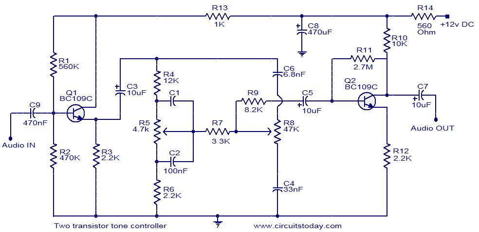
This 15 Volt and -15 Volt is given to the TL072C. This is a inexpensive high fidelity hi-fi tone control circuit designed just with two low cost transistors as the active components. Take a note that you must connect the circuit before the amplifier module.
This electric circuit is based on the well-known Baxandal tone control plan. This circuit is based on the famous Baxandal tone control design. Bass tone circuit diagram.
We are using IC7815 and IC7915 to get the 15 Volt and -15 Volts. The transistor amplifies this small current to allow a larger current to flow through from its collector C to its emitter E. Transistor Q1 is configured in a simple emitter-follower buffer stage which provides the device an increased input impedance.
This is a Bass tone circuit diagram using one transistor c828. Admin March 9 2020. Electrical schematics diagram shown below is a simple two transistor tone controller audio circuit free pictures for download.
A tone control circuit is an electronic circuit that consists of a network of filters which modify the signal before it is fed to speakers headphones or. Take a note that you should connect this circuit before the amplifier circuit. The bass control basically allows only the lower range of the frequency ideally between 10Hz and 300Hz that means the user can adjust this pot to cut off all.
Bass tone circuit diagram. Tone control circuit. The key element to the multi-tone generator is the 2N2646 transistor.
The design is an active tone control circuit that delivers frequency-selective negative feedback to. Here is the circuit diagram of a simple two transistor tone controller circuit. Which low quality than Active tone control.
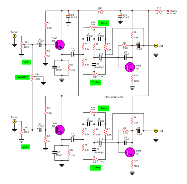
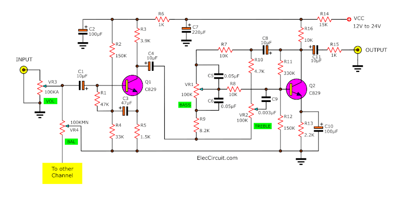
The schematic is one channel mono tone control build the similar circuit will make it become stereo channel. The second transistor is used to voltage amplify the signal in. 0 59 1 minute read.
Every amplifier needs this circuit to control the sound. The diagram shows the two current paths through a transistor. You can use transistor BC549C or other NPN transistors such as European equivalent.
Its run with 12 voltages. The output of tone control must be connected to the input of the amplifier. When the switch is closed a small current flows into the base B of the transistor.
Seetharaman Subramanian and time it is a high quality passive tone control circuit that has an overall gain of around 25 with 20dB boost and cut. This circuit one of the best bass tone control circuits. Deviation in the value of these electrical circuit transistor components varies the audio response of the system.
For OP-AMP in the Audio Tone Controller Circuit we require two supplies 15V and -15V. Two transistor tone control circuit. This is Bass treble tone control circuit diagram as ideas.
Connection diagram of this circuit is shown below. Volume bass high tone. The circuit build based on ordinary tone control circuit using two low cost transistors FCS9014 in each channel so there are will be four.
It is just enough to make LED B glow dimly. The transistor Q1 is wired an emitter follower to provide sufficient current gain and input impedance. This circuit is very cheap to build and its commonly implemented in.
LM2931-50 is a Random Noise Generator too Schematic Circuit Diagram. This circuit needs minimum number of components is very cost effective and most of the components required can be found from you junk box. 12V Stereo Tone Control.
The schematic is one channel mono tone control build the similar circuit will make it become stereo channel. Two NPN transistors BC107 are used in this circuit this circuit is biased by 30 volt DC power supply Audio input taken through the 22μfd capacitor and separated into two lines to control bass and treble effects output from the tone control elements are fed into transistor pre amplifier output is synchronized and then fed into the output pins here the output is taken from second transistor. The circuit build based on ordinary tone control circuit using two low cost transistors FCS9014 in each channel so there are will be four transistors in this 12v stereo tone control.
The circuit build based on ordinary tone control circuit by using two transistors FCS9014 in each channel so there are actually four transistors in this stereo audio tone control. This Hi-Fi tone control circuit can be operated with wide range supply voltage 12V 24V DC. Simple 2 Transistor Headphone Amplifier.
Assume that when the DC is applied to the given circuit the T1 transistor is conducting with the current passing through the N2 and R1 resistors at the first moment. We have two circuits both transistors OP-AMP as main so smaller but high gain signal. Henceforth the transistor in this circuit with a minimum list of components gives the best result as a tone generator.
This is a inexpensive high fidelity hi-fi tone control circuit designed just with two low cost transistors as the active components. Capacitor C2 connects the Q1 output with the tone control circuitry. If we use this circuit diagram.
The discussed bass treble tone controller circuit thus effectively performs like a 3 band graphic equalizer circuit allowing the user with distinct 3 way control of the sound frequency. This is the schematic diagram of very simple headphone amplifier circuit. We can get both supplies from dual power supply circuit.
BC548C BC547C BC239 2N5818 or 2N2222. This is just another circuit designed by Mr. Baxandall Tone Control Using Two Transistors.
This tone control circuit use very popular Baxandall configuration a simple circuit configuration that provides boost and cut control in continuous manner. You used to see the Passive tone control circuit.

7 Tone Control Stereo Preamplifier Circuit With Pcb Low Noise Eleccircuit

Stereo Tone Controller With Transistors One Transistor

7 Tone Control Stereo Preamplifier Circuit With Pcb Low Noise Eleccircuit

Two Transistor Tone Controller