This condition causes either a long overload or DC accuracy errors. Create a project called Peak Detector and draw the circuit in Fig.

Ltc6244 High Speed Peak Detector Analog Devices
Low input offset voltage and current.

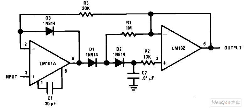
Low Drift Peak Detector Circuit. One point to observe is input bias of the OPs. Peak Detector OTRA current mode circuits. Low Drift Integrator TLH705757 Q1 and Q3 should not have internal gate-protection diodes.
Open the circuit in the CircuitLab editor and press F5 to run the time-domain simulation. The ideal peak detector performs this function regardless speed of the input signal. LM358 are one of LM158 series op amps which operates over a wide range of power supply voltage.
Though this circuit is effective and works well it is only good for rough estimates and lacks high precision. A track-and-hold peak detector circuit which can operate at low input signal frequencies includes a capacitor to hold a peak voltage of the input signal and logic circuitry that reduces an effect of leakage current into or out of the capacitor and therefore provides protection against self-switching of an output signal of the peak detector circuit. Wide common mode input voltage range including grounding.
In principle one can also use 2 diodes in series with the version from 4. So long as the GBW and frequency response of the OPA1642 is fine for the signal youre peak detecting itll work. In the positive half cycle diode D is forward biased and capacitor C starts charging.
If the peak detection is to function on both positive and negative half cycles and they can be very different a precision rectifier is used in front of the peak detector. Most OP Amps with JFET inputs are low input bias current types which means the inputs dont drain a lot of current generally in the low nA to pA range. However by adding an op-amp with feedback around the diode we can eliminate the diode voltage drop and end up with a much more linear peak detector at the cost of a few extra.
If you use a 4th opamp to buffer the 25V reference point then you can connect all the points requiring to be biased at mid rail to the output of that opamp because it looks like a low impedance voltage source. Peak Detection Circuits Precision rectifiers have been discussed in AN001 and here is another common circuit is used to detect the peak of an AC waveform. A low drift peak detector circuit diagram using LM358 is shown in the following picture.
This would be ideal if youre trying to peak detect a very low frequency signal. NI Multisim Live lets you create share collaborate and discover circuits and electronics online with SPICE simulation included. A diode plus capacitor can form an essentially passive peak detector.
All voltage below 0V is clipped because the diode only allows current flow in the forward direction and not the other direction. Fast Summing Amplifier with Low Input Current TLH705758 In addition to increasing speed the LM101A raises high and low frequency. High DC voltage gain about 100dB.
The output stage must have a high slew rate in order to keep up with the intermediate stages of the amplifier. When input reaches its peak value capacitor gets charged to positive peak value. So far here are mainly 2 types of peak detector shown.
Peak detector circuits are used to determine the peak maximum value of an input signal. It detects the peak voltage only on the positive side of the AC signal. Fast peak detectors place unusual demands on amplifiers.
Richard Markell in Analog Circuit Design 2013. You need to set up an initial condition IC on the capacitor C1 by using an IC1 part from the special library. It stores the peak value of input voltages for infinite time duration until it comes to reset condition.
Low Drift Peak Detector Circuit Diagram using LM358 Op Amp. Worst case drift less than 500 mVsec over b55Ctoa125C. A simple single Rgnd for the peak detector can then be connected to this 25V source.
This is achieved by peak detector circuit. Rename the SCHEMATIC1 folder to Peak Detector. This is a peak detector circuit that can detect the peak of an input analog signal with more precision than a simple peak detector.
If you are using the demo CD use the uA741 opamps. Mainly the one with 2 diodes in series for a low drift version and in reply 4 a fast version with slightly better precision the offset error of the 2 nd OP is compensated. To make a distinction this peak detector circuit functions as a positive peak detector.
In response to Conflicting impedancies in peak detector. Although this peak detector circuit implement diode forward bias compensation the circuit is still not accurate enough for the input level below 100mV you need a more precise peak detector circuit if you concern with such low level signal. LM358 Application circuit diagram.
Note that with this circuit the peak detector output will always be centred on 25V. AC-401 MC1741CD SSFDFMM-TTL34G IC41C16256-50K MEH78ZAX-R SN-R. Ideally the output of the peak detector circuit tracks or follows the input voltage until the extreme point is reached but holds that value as the input decreases.
This proposed circuit is simulated using PSPICE simulation for which OTRA is realized using 180 nm CMOS process with low power supply of 09V. The performance of the physical peak detector is limited by the bandwidth of the input signal. Previously weve shown how to build a peak detector circuit using only the simple components of a diode and a capacitor.
Low input bias current. This 06 voltage drift make the diode ready to conduct although the input signal is exacly at zero. Heres an inexpensive precision peak detector circuit that accurately tracks the peak voltage of input signals at frequencies up to 100kHz and has zero volta.
The peak detector circuit utilizes its property of following the highest value of an input signal and storing it. The differential mode input voltage range is wide equal to the power supply voltage range. LM358 Characteristics of Features.
The proposed circuit also provide very low power dissipation. The following figure shows a simple peak detector circuit using diode and capacitor. This paper peak detector is proposed using low voltage OTRA.

Ltc6244 High Speed Peak Detector Analog Devices
Low Drift Peak Detector Circuit

Low Drift Peak Detector Circuit Measuring And Test Circuit Circuit Diagram Seekic Com
Detector Circuits An Overview Sciencedirect Topics