I used RFD16N05L MOSFETs. We use Astable Multivibrator by transistors and other parts.
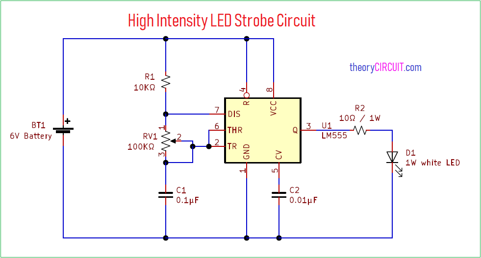
High Intensity Led Strobe Circuit
To create an LED flasher circuit the parts which we need to do so are.

Make High Power Led Flasher. GPIOoutput14 GPIOLOW Making the LED flash is simple to do. Drill a 5mm hole for the LED in the project box. Hello Guys today in this video I will show you How To Make LED Flasher CircuitVisit my Website for Buying Links more Information about LED Flasher Circui.
This is Super Blinking Two LEDs circuit. In this project let us develop an LED Strobe light circuit using the popular 555 timer IC. Tylers build starts with some high-quality LEDs which cost him around 7 each.
Build a simple LED flasher and find ways to use it for decoration. The circuit has an approximate ON state time of 094 Seconds and OFF state time of 047 Seconds. Thats 11000000th of a second.
This circuit is easy and cheap. When the above sets of facts are put together it transpires that the ideal micropower LED flasher when using a Super Bright LED should produce a pulse with a duration d of 10mS at a current I of 2mA at a repetition period p of 2 seconds 2000mS. It makes LEDs uniform brightness but use all current are 04A to 06A.
Adding another simple highly efficient flasher IC to the mix. Now and then AAC gets a request for a flasher for the relatively new high power LEDs. When the two switch wires are open power is passed directly from the power source to the LED driver causing the LED to be full on.
This is why this mode is also called oscillator mode because it uses the 555 timer an oscillator which creates square wave signals. Testing When completed circuit assembly Supply voltage range of 15V to the circuit. First we try out the circuit on a breadboard.
Read more about an Easy high-power LED blinking circuit. A very interesting light fading effect can be achieved by wiring up the IC 555 circuit as per the diagram shown below. This is an 8-pin DIP IC though SMD equivalents are available too.
We are designing this circuit using a 555 timer for setting the delay between each flash and a high power LED light as the source of light. The All LEDs will lit the circuit is ready for use. Remember to compile and program the AtTiny using the 1MHz option.
Some will even let you go as short as around 130000th of a second. Check the electronic components you need here. Through a collaborative effort between myself SgtWookie and turntj weve come up with something fairly open ended which should be easy to modify for other people attempting something similar.
It switches constantly between high and low or on and off. But sometimes even that isnt fast enough to freeze super fast movement. When the two switch wires are connected the flashing module causes the LED to flash at the selected.
The circuit of a simple LED wig wag flasher presented here incorporates just a couple of transistor and is wired as a multivibrator. Insert the AtTiny into the IC socket. NTE876 LED flasher oscillator operates from 115 to 6 Volts delivers up to 2 Volts to the connected LED at up to 45 mA and needs an operating current of merely 075 mA maximum.
To turn GPIO14 on we use the following command. If the LEDs are too bright or stuff gets hot use a higher value. It has high power out to load 12V light bulb with source voltage form a 12V battery or DC supply at current 2A up.
The LuxDrive D004 Flasher module connects between the power source and LED Driver to provide flashing for LEDs. Then slide the switch to position ON. LED Strobe Light Circuit.
We hope you like it. There you must have studied how a transistor can be used to switch a load connected to its collector through a small voltage applied to its base. 9-volt Battery or DC power supply.
Tylers goal was to create a single microsecond flash duration. This will also allow you to tweak the value of R2 to your liking if the LEDs are not bright enough use a smaller value like 3 Ohms. Figure 1 Simple High power LED flashlights the circuit diagram We used 1 ohms resistor for limit current to save This circuit we use 3x AA 12V x A nickel-metal hydride battery.
Now that we have confirmed that our circuit will not damage the Pi lets get this LED flashing. The Rate of flashing of the circuit can be calculated as T on 069 R1 R2C. GPIOoutput14 GPIOHIGH To turn GPIO14 off we use the following command.
Light Fader Circuit Using IC 555. The circuit switches ON the LED very gradually and does the same while switching it OFF that is. A strobe light or a stroboscopic lamp is one which can produce regular flashes of light.
How To Make A Simple 12V High Current LED Light Flasher Circuit - YouTube. This time its an easy way to control high-power LEDs. Secure the vero board and LED to the project box.
5 Ohms should be safe for most LEDs. Add the two batteries and make sure LED is flashing. Here circuit consists of an astable multivibrator using an NE555 timer IC which generates a square wave.
The LED can be soldered directly onto the board or via two wires. Figure 5 The High power 6 LED Flashlight projects for 15V AA battery. It just needs one external capacitor for timing adjustment the R of the RC.
And two transistors-2SC1061 or TIP41 for drive load up to 10 watts. They came up with a simple circuit that uses a blinking bulb from a string of holiday lights instead of something like a 555 IC or micro-controller.

Diac Controlled Led Flasher
Super Bright Led Flasher Electronics Lab Com
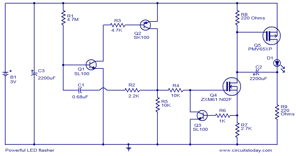
Powerful Led Flasher
Make High Power Led Flasher
