A Monostable 555 Timer is required to produce a time delay within a circuit. This circuit consists of 2 switches one for start the delay time and other for reset.
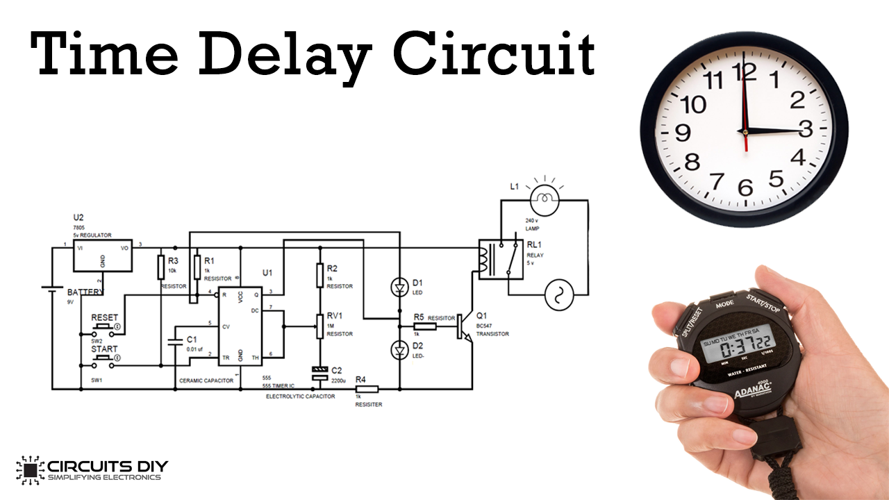
Simple Time Delay Circuit Using 555 Timer
Additional Timing from Microseconds through Hours terminals are provided for triggering or resetting if Operates in Both Astable and Monostable Modes desired.
Time Recovery Delay Circuits Lm555. Circuit is used to drive 2 relays in parallel. Circuit Delay diagram Electronics LM555 part 29 Schematic Stage Time Two LM555 Electronic Schematic Diagram Variable period Oscillator CD4017 part 30 LM555 Electronics Schematic Diagram Triggering And Timing Helpers For Monostable Timers part 28. There is a delay before the output turns off.
Overall these circuits demonstrate the flexibility of the 555 and 556 timer integrated circuits. The parts values in these circuits were selected for testing purposes and can be adjusted to suit the needs of a particular application as long as the normal operating parameters of the LM555 are maintained. Resistors R1 and R2 were selected first and thenresistor R3 was selected to give the best control range based onmeasurements at.
Connected Appliance with this timer circuit is automatic switch OFF after some duration of time. Power up delay Try circuit as per attached drawing. The output stays on for a few seconds and then turns off.
In this Time Delay Relay Circuit the 555 Timer is used in the Monostable Mode. The second 555 timer helper will extend the timers output duration without having to use large values of R1 andor C1. The duty cycle adjustment range ofthis circuit is from 42 to 55 percent.
It also has a potentiometer to adjust the time delay where you can increase of decrease the time delay. The 555 Timer IC is a popular 8-pin Integrated circuit chip that can be used in a variety of timing and pulse generation applications. If a 10uF timing capacitor is used calculate the value of the resistor required to produce a minimum output time delay of 500ms.
Is also a short delay in the recovery of the trigger terminal voltage. Long time delays in a variety of applications has lured many designers from mechanical timers op amps and various discrete circuits into the ever increasing ranks of timer users. No doubt the heart of this circuit is 555 Timer IC.
The delay duration can adjusted with the changing the value of R2 and Capacitor c2. Have configured it in astable mode with pin 5 7 open. To estimate R and C values you can goto.
If the switch is opened before 10 secs the timer should reset back to zero. It functioned as expected. Posted 2008-Jun-30 539 pm AEST.
The LM555 is a highly stable device for generating accurate time delays or oscillation. I have made an on-time delay timer circuit using the LM555 with R-15Mohms and 47uf as time determinant. The IC can operate in three different modes such as Astable Monotstable and Bistable because of which it can be adapted into many types of circuit designs like time delay circuits pulse generation circuit oscillator circuit and much more.
Archive View Return to standard view. The LM555 timer can achieve a 50 percent dutycycle as shown in the next diagram. DESCRIPTION The 555 timer consists of two voltage comparators a bistable flip-flop a.
The output relay should only become energised if the switch is held closed for 10 secs LM555 would be ideal. A delay before turn off circuit is a circuit that once you apply power to it turns on the output right away. Last updated posted 2008-Jul-3 525 pm AEST posted 2008-Jul-3 525 pm AEST User 189891 1103 posts.
Need Help for 555 Time Delay Circuit. The timing of the delay can also be changed by changing the resistor value of VR1 and the capacitor value of E based on the time delay formula of t069RC. This circuit is used to generate time delay circuits like Time delay relay one-shot operation of the load in sensor based load switching like PIR sensors etc.
The other main components are the resistors R1 R2 Pushbutton S1 Capacitors C1 C2 Diodes and a 12V SPDT type relay. Time Delay Circuit Time Delay Using 555 Timer DIY Electronics Project - YouTube. Additional terminals are provided for triggering or resetting if desired.
This circuit uses a 555 timer to delay a pulse that comes in to a maximum time of 75 seconds. In this circuit we will show how to build a delay before turn off circuit with a 555 timer chip. The Changing of capacitor value is not easy so only the changing of value of the resisitor by variable resistor preset is connected with the circuit to setting the delay time duration delay time.
The LM555 is a highly stable device for generating 1 Direct Replacement for SE555NE555 accurate time delays or oscillation. Time Delay Circuit Time Delay Using 555 Timer DIY Electronics Project. One triggs 555 second disables the RLY for a short period of time after power is applied.
In the time delay mode of operation the time is precisely controlled by one external resistor and capacitor. A delay before turn off circuit can be useful for any circuit that needs to be on only for a short period of time. In other words i want a circuit that will do the following I push the trigger then there is a time delay where the LED is off then after the delay.
By connecting a 18K ohm resistor between the supply voltage and pin 5 of the 555 timer chip the output pulse duration will approximately be doubled. Astable Multivibrator using 555-Timer The monostable circuit is modified to re-trigger itself by connecting trigger terminal and threshold terminal. I want a 555 timer circuit diagram which will result in turning an LED ON AFTER a time delay but staying on permanently.
There are additional 2 associated circuits based on transistors. In the time delay mode of operation the time. 500ms is the same as saying 05s so by rearranging the formula above we get the calculated value for the resistor R as.
When a switch is closed the time should start. In this project we are going to design a Simple Time Delay Circuit Using 555 Timer IC.

Adjustable Timer Circuit Diagram With Relay Output Circuit Diagram Electronic Schematics Timer

Time Delay Relay Using 555 Timer Ic
Timer Using Lm555

555 Lm555 Timer Pinouts And Tutorials